

Color liquid crystal display device and color liquid crystal display apparatus
- Summary
- Abstract
- Description
- Claims
- Application Information
AI Technical Summary
Benefits of technology
Problems solved by technology
Method used
Image

Examples
first embodiment
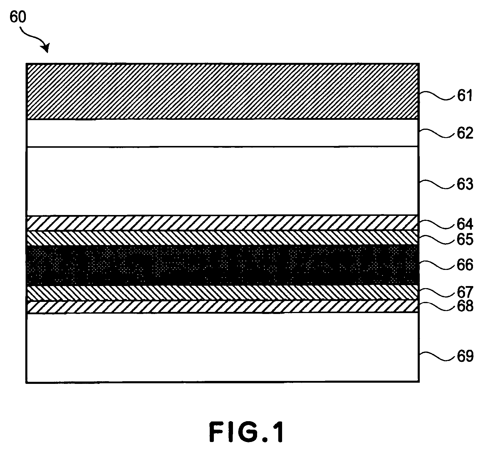
[0063]FIG. 1 is a schematic sectional view showing a structure of a reflection-type liquid crystal display device as an example of the color liquid crystal display device according to the present invention used in a color liquid crystal display apparatus.
[0064] Referring to FIG. 1, a reflection-type liquid crystal display device 60 comprises a lamination structure including a polarizer 61, a viewing angle compensation film 62 as a phase plate, a first glass substrate 63 as a first substrate disposed on an observer side, a transparent electrode 64, an alignment film 65, a liquid crystal layer 66, an alignment film 67, a reflection electrode 68, a second glass substrate 69 as a second substrate disposed opposite to the first glass substrate 63.
[0065] Incidentally, the reflection electrode 68 may be provided with an unevenness by a known method so as to possess divisibility or may be provided with a front scattering film disposed between the viewing angle compensation film 62 and the...
second embodiment
[0104] Hereinbelow, Second Embodiment will be described. In this embodiment, the phase compensation plate used in the present invention is applied to a liquid crystal in an optically compensated bend (OCB) mode. A basic concept in this embodiment is similar to that in First Embodiment. Thus, in the following, different points will be principally described.
[0105] A basic structure of an OCB-mode liquid crystal display device is similar to that of the VA-mode liquid crystal display device shown in FIG. 1. In the OCB mode, different from the VA mode, a liquid crystal material having a positive dielectric anisotropy is used. Further, in order to realize bend alignment, the alignment treatment (rubbing treatment) is performed in the horizontal direction and an alignment change treatment (transfer treatment) from splay alignment to bend alignment is performed by a known method. In the thus prepared OCB-mode liquid crystal display device, when a voltage not less than a predetermined bend ...
example 1
[0148] A reflection-type liquid crystal display device is prepared in the same manner as in Comparative Example 2 except that a C plate is disposed between the front scattering plate and the wide-band circular polarizer.
[0149] In this example, a retardation of the C plate providing a minimum value of a color difference varying depending on a viewing angle during ECB effect-based color display is determined by changing the retardation of the C plate from −500 (nm) to +500 (nm).
[0150] When ΔE (color difference) is measured by changing the retardation of the C plate from −500 (nm) to +500 (nm), a minimum ΔE is generally obtained at positive retardation values during both red display and blue display although it varies depending on the incident direction of light.
[0151] In the case where the incident direction of light is the inclination angle direction of pretilt, a retardation of the C plate providing a minimum color difference during red display is about −100 nm and a retardation ...
PUM
 Abstract
Description
Claims
Application Information