Method and apparatus for oculomotor performance testing

a technology for oculomotors and ocular motors, applied in diagnostic recording/measuring, instruments, applications, etc., can solve problems such as error distorting actual, device deficiency in many respects, and device inability to record and/or compare differences between the time it took to move in any one specific direction and any other specific direction, so as to increase the stability of the accessory, increase the movement area, and increase the effect of movement area

Inactive Publication Date: 2005-08-04
HARBIN GARY LYNN +1
View PDF22 Cites 9 Cited by
  • Summary
  • Abstract
  • Description
  • Claims
  • Application Information

AI Technical Summary

Benefits of technology

[0016] The cross-sectional view illustrated in FIG. 4 provides a more detailed perspective of certain preferred aspects of present invention. The pad preferably includes a base portion which rests upon the switch which in turn is placed upon a switch holder or block. The base portion of the pad is located beneath the top sheet or cover for the board panel. The pad further includes a raised portion positioned atop the base and this raised portion preferably is positioned such that the top surface is on a slightly higher plane than the top sheet of the board panel. In even more preferred forms, the raised portion of the pad includes some type of a traction-increasing substance or surface such that a test subject moving quickly from pad to pad will not slip. Additionally, the preferred construction permits relative movement between the pad and the frame or top sheet such that when weight is placed upon the pad, the pad depresses the switch upon which it sits until the base portion of the pad contacts a shoulder which is cut into the frame. When the weight is removed from the pad, the switch and pad elevate from the shoulder and return to the original position of an unweighted pad.
[0028] In yet another embodiment of the invention, a stabilizing accessory for semi-ambulatory individuals is provided. The accessory assists individuals that desire or need assistance in standing during the performance of testing using the above-described inventions. The accessory generally comprises a frame that provides support to an individual leaning thereon. Preferably, it includes a plurality of legs on one end that extend to the floor and a handle portion at the opposite end. Preferably, the frame provides an individual with enough room to perform the movements required during the testing with a minimum amount of interference. Still more preferably, the accessory is provided with a base that increases the stability of the accessory during testing. In one such embodiment, the accessory comprises two inverted U-shaped members interconnected with at least one crossbar. The crossbar is arched so as to provide an increased movement area to an individual using the accessory. Each of the U-shaped pieces also includes at least one arched crossbar connecting the two leg sections of the U-shaped members. Again, the crossbar is arched outwardly away from an individual using the accessory. The central section of each member has a grip portion adapted to be used as a handle by an individual. The end of each leg section opposite the central section terminates in a base. One particularly preferred base comprises an ANVER (Hudson, Mass.) vacuum or suction cup member equipped with a pivoting suction initiator and release lever. In a particularly preferred embodiment, the accessory is a conventional walker that has been modified to provide an increased area for movement and which includes a suction cup foot at the end of each leg. As with conventional walkers, the device is height-adjustable through a series of push-in detent projections and cooperative holes that permit the handle portion to telescope into the leg sections. The arched configuration of the crossbars increases an individual's movement area between the two U-shaped members so that the testing can be performed with a minimum amount of interference resulting from use of the accessory. In preferred forms, the stabilizing accessory will able to be broken down and pivoted together in order to facilitate storage thereof. In this form, each of the individual components may be disconnected and stored or portions of the accessory will be disconnected and the remainder of the device will be pivoted together. For example, the crossbar connecting the two U-shaped members may include a pivoting portion which permits the U-shaped members to moved into close proximity with one another, thereby decreasing the amount of space required for storage of the accessory.

Problems solved by technology

This device was deficient in many respects including: 1) There was only one switch per panel which required the test subject to step into the center of the panel in order to insure that the switch would activate and send a signal to the computer collecting the data.
2) When a series of prompts were given, the device could not record and / or compare differences between the time it took to move in any one specific direction and any other specific direction.
Thus, incorrect movements could skew the results.
Thus if the testing consisted of the total elapsed time required for a series of prompts followed by movements, an error may distort the actual results as the time taken during these movements would be added to the total time.

Method used


Image

  • Method and apparatus for oculomotor performance testing
  • Method and apparatus for oculomotor performance testing
  • Method and apparatus for oculomotor performance testing

Examples


Embodiment Construction

[0044] The following description sets forth preferred embodiments of the present invention. It is to be understood, however, that this description is provided by way of illustration and nothing therein should be taken as a limitation upon the overall scope of the invention.

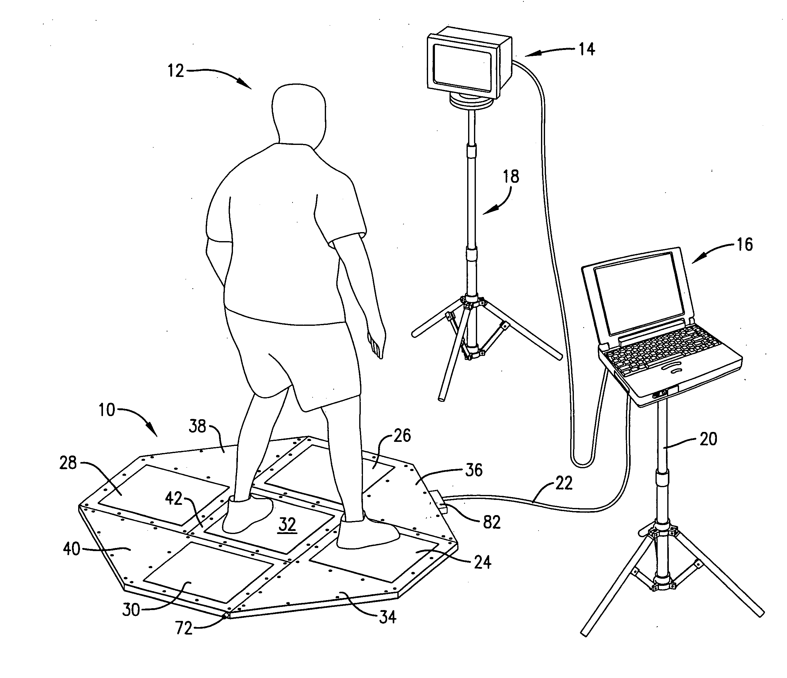
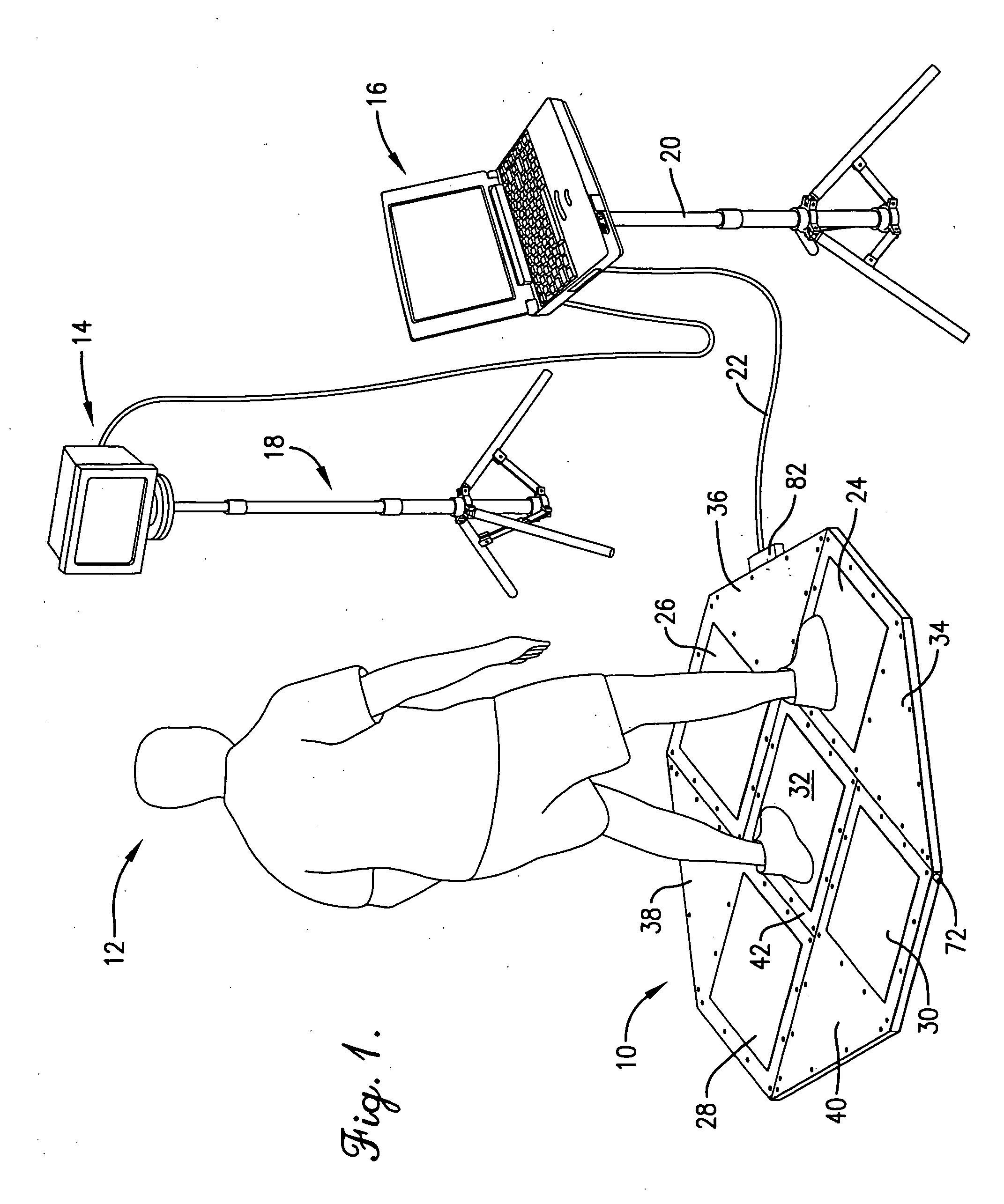
[0045] Turning now to the drawings, a preferred oculomotor testing device 10 is illustrated in FIG. 1. A test subject 12 is standing upon the device 10 facing a monitor 14 which is electrically connected to a computing device 16 in the form of a portable computer. Monitor 14 and computing device 16 are positioned atop respective stands 18, 20. Oculomotor testing device 10 is in the shape of an octagon and is also electrically connected to computing device 16 through cord 22. Testing device 10 presents four perimeter pads 24, 26, 28, 30, surrounding a central pad 32. Pads 24, 26, 28, 30, 32 can be of any shape and size and one preferred shape is square.

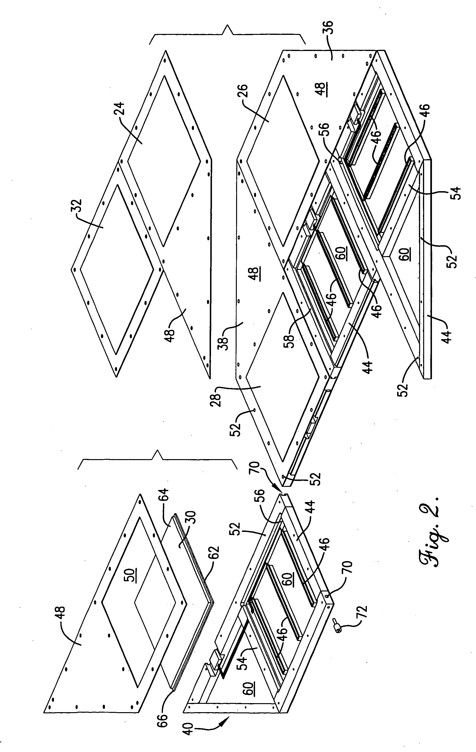
[0046] As shown by FIG. 2, each respective perimeter pad sits...


PUM


Abstract

The present invention provides improved oculomotor testing devices and pain tolerance testing devices. Certain oculomotor testing devices test parameters including response time, reaction time, and movement time, as well as precision. The devices are adapted for ambulatory as well as semi-ambulatory and non-ambulatory individuals. Methods of using the devices are provided wherein a visual stimulus is provided and the individual is instructed to perform a movement specific to that visual stimulus. Preferably, the device records the movement done in response to the visual stimulus and, with the aid of a computing device, factors out errors and measures the desired parameter. One embodiment of the present invention permits a user to observe a real-time visual feedback of the force exerted on a load cell. The individual can increase or decrease the amount of force exerted in response to the display of force on a visual feedback monitor. Such a device can measure the pain tolerance of an individual by correlating the length of time the individual can maintain a certain exerted force on the load cell with their tolerance for pain.

Description

RELATED APPLICATIONS [0001] This application is a divisional application of application Ser. No. 10 / 761,182, filed on Jan. 20, 2004, the teachings and content of which are incorporated by reference herein.BACKGROUND OF THE INVENTION [0002] 1. Field of the Invention [0003] The present invention is broadly concerned with devices used in physical testing including oculomotor testing and methods of testing using these devices. More particularly, one embodiment of the present invention is concerned with an oculomotor testing device which can measure a variety of parameters associated with oculomotor response and methods of oculomotor response assessment using this device. Still more particularly, the present invention is concerned with an oculomotor testing device which comprises a plurality of panels having switches which are electrically connected to a computing device. The switches are underneath a pad whereby the switches are activated upon weight being applied to the pad. Even more ...

Claims


Application Information

Patent Timeline
Patent Type & Authority Applications(United States)
IPC IPC(8): A61B5/103A61B5/16
CPCA61B5/103A61B5/1116A61B5/162A61B5/6887A61B2562/046A61B2562/222A61B2562/0252A61B5/4023A61H3/00A61H2201/013A61H2201/1635
Inventor HARBIN, GARY LYNNREDDEN, WARREN
Owner HARBIN GARY LYNN
Why Eureka
Try Eureka