Electrochemical energy store

a technology of electrochemical energy and storage cells, applied in the field of electrochemical energy stores, can solve the problems of difficult connection of individual storage cells and channels in heat exchange units, difficult construction process and overall installation of battery boxes, and disadvantages of prior art electrochemical energy store design relatively complicated, etc., to achieve the effect of simplifying the installation in the battery box

Inactive Publication Date: 2005-08-04
DAIMLER AG
View PDF6 Cites 72 Cited by
  • Summary
  • Abstract
  • Description
  • Claims
  • Application Information

AI Technical Summary

Benefits of technology

[0006] The present invention provides an energy store having a structure arranged and configured to facilitate a simplified installation in a battery box.
[0007] In a preferred embodiment of the present invention an electrochemical store comprises a plurality of heat exchange units and a plurality of electrochemical storage cells arranged in an array, alongside one another, and between pairs of the heat exchange unit. The heat exchange units include heat exchange channels for flow of a temperature control fluid. A forward flow distribution channel is coupled to the heat exchange channels for ingress of the temperature control fluid and a return flow distribution channel is coupled to the heat exchange channels for egress of the temperature control fluid flow. Pursuant to a feature of the present invention, the plurality of heat exchange units are coupled to one another to form a self-supporting electrochemical store unit suitable for insertion into a battery box as a unit.

Problems solved by technology

The prior art has the disadvantage of a relatively complicated design of the electrochemical energy store, with a large number of modules and storage units, and heat exchange units which are in each case arranged between them.
Owing to the installation of the individual modules and of the heat exchange units, the construction process and the overall installation in the battery box are very difficult.
For example, it has been found that the connection of the individual storage cells and channels in the heat exchange units is often highly dangerous and difficult, owing to the high potential of the modules.
In this case, screw connections for the connections of the individual parts, for example of the storage cells, must, inter alia, be tightened to a defined torque, which is frequently inconvenient and difficult owing to access and space restrictions.
However, mounting openings such as these are problematic for fire protection reasons and for EMC protection (electromagnetic radiation).

Method used


Image

  • Electrochemical energy store
  • Electrochemical energy store
  • Electrochemical energy store

Examples


Embodiment Construction

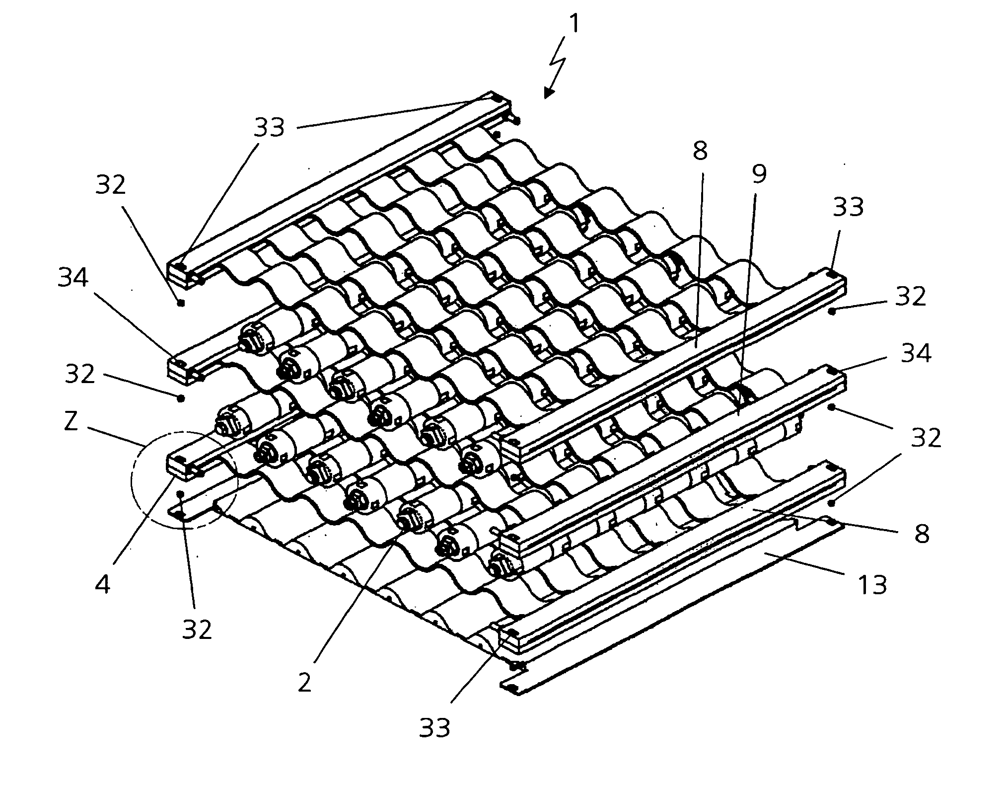
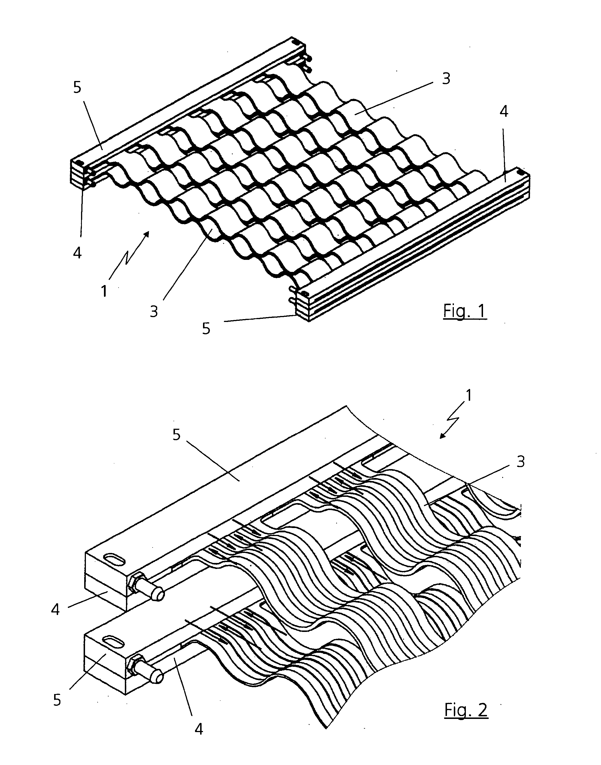
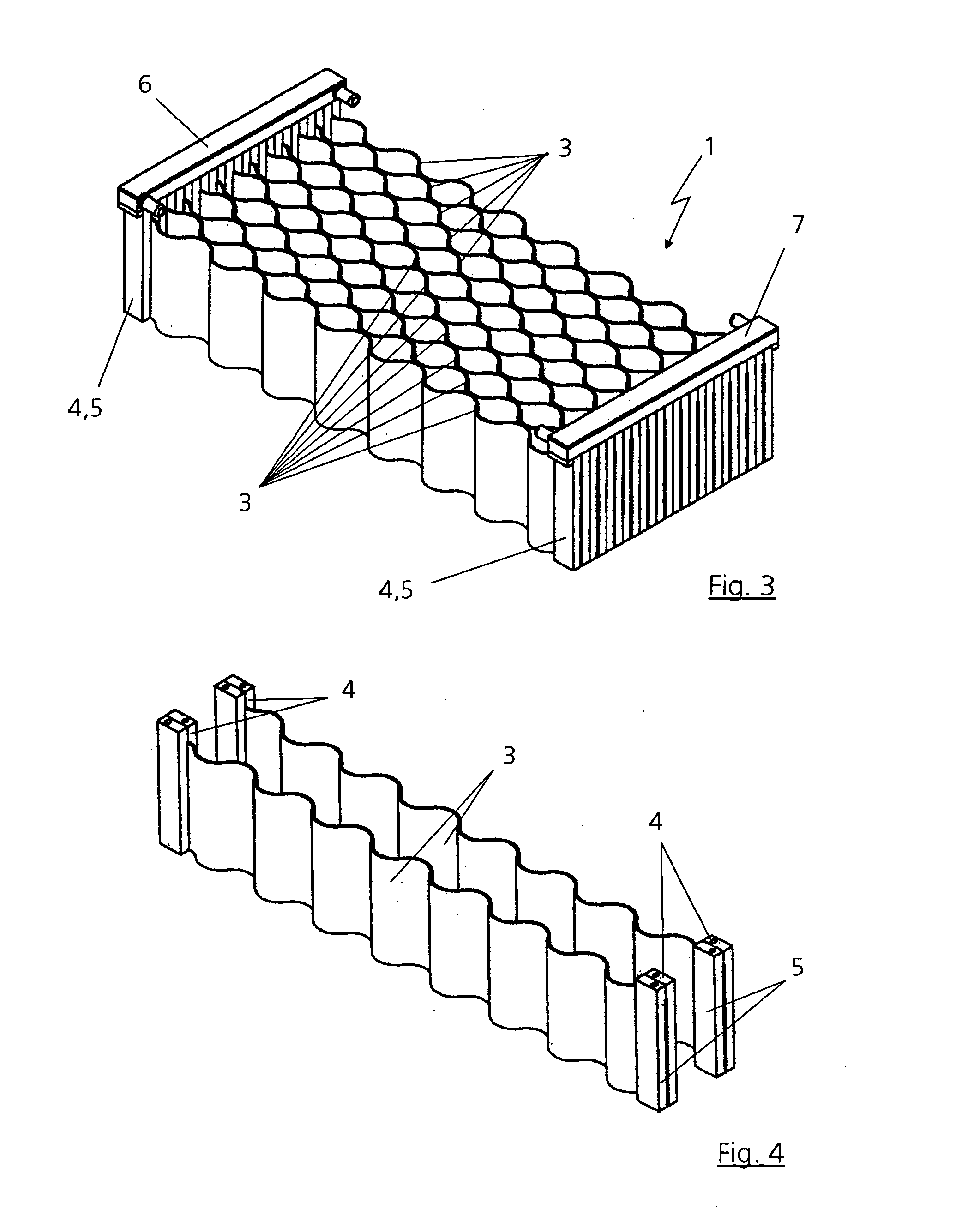
[0043] FIGS. 1 to 5 show the general design features of an electrochemical energy store. Since such an electrochemical energy store is, in general, known from the prior art, only the major parts will be described in more detail in the following text. In principle, the energy store may be designed as required by a respective application. However, according to a feature of the present invention, the energy store is designed as a self-supporting unit, as will be described in more detail in the following text.

[0044] A plurality of heat exchange cooling units 1, between which storage cells 2, for example Ni / MeH cells, are arranged, is provided in the energy store (see, for example, FIGS. 12 and 13). As shown in FIG. 1, the heat exchange units 1 are designed, for example, with six circulation channels or heat exchange channels 3. A temperature control fluid is circulated through the heat exchange channels 3. The flow runs in either direction on a plane and in either direction parallel to...


PUM

PropertyMeasurementUnit
temperaturesaaaaaaaaaa
temperatureaaaaaaaaaa
pressureaaaaaaaaaa

Abstract

An electrochemical store is provided. The electrochemical store comprises a plurality of heat exchange units and a plurality of electrochemical storage cells arranged in an array, alongside one another, and between pairs of the heat exchange unit. The heat exchange units include heat exchange channels for the flow of a temperature control fluid. A forward flow distribution channel is coupled to the heat exchange channels for ingress of the temperature control fluid and a return flow distribution channel is coupled to the heat exchange channels for egress of the temperature control fluid flow. Pursuant to a feature of the present invention, the plurality of heat exchange units are coupled to one another to form a self-supporting electrochemical store unit suitable for insertion into a battery box as a unit.

Description

[0001] This application claims priority to German Patent Application DE 10 2004 005 394.4, filed Feb. 4, 2004, which is hereby incorporated by reference herein. BACKGROUND [0002] The present invention is directed to an electrochemical energy store. [0003] An electrochemical energy store of a type relevant to the present invention is described in WO 02 / 07249 A1. A development of this type of energy store is also described in German Application P 102 382 35.2. With regard to further prior art, reference should be made to EP 065 349 B1 and DE 198 49 491 C1. The German reference DE 197 27 337 C1 describes a venting closure for electrical housings. [0004] The prior art has the disadvantage of a relatively complicated design of the electrochemical energy store, with a large number of modules and storage units, and heat exchange units which are in each case arranged between them. The energy store together with the individual modules is assembled in a battery box to which the entire unit is...

Claims


Application Information

Patent Timeline
Patent Type & Authority Applications(United States)
IPC IPC(8): H01M8/04B29C65/16F28F3/12F28F9/26H01M10/50H01M50/213H01M50/262H01M50/291
CPCB29C65/16B29C66/54B29L2031/18F28D2021/0077F28F3/12F28F9/26H01M10/5095H01M2/1077H01M10/5004H01M10/5016H01M10/5075H01M10/5077H01M2/022H01M10/625H01M10/663H01M10/6568H01M10/6567H01M10/613Y02E60/10H01M50/107H01M50/213H01M50/291H01M50/262
Inventor GERMAN, JOHANNSOCZKA-GUTH, THOMAS
Owner DAIMLER AG
Why Eureka
Try Eureka