Stacked membrane for pressure actuated valve

Inactive Publication Date: 2005-08-04
NAVILYST MEDICAL
View PDF62 Cites 59 Cited by
  • Summary
  • Abstract
  • Description
  • Claims
  • Application Information

AI Technical Summary

Benefits of technology

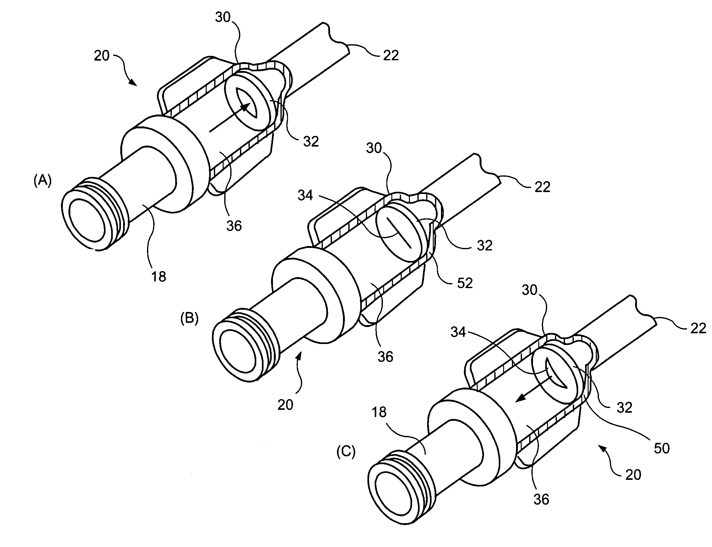
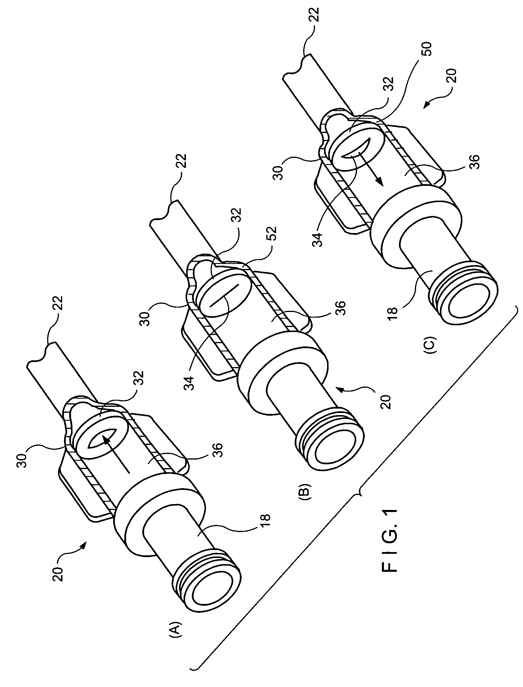
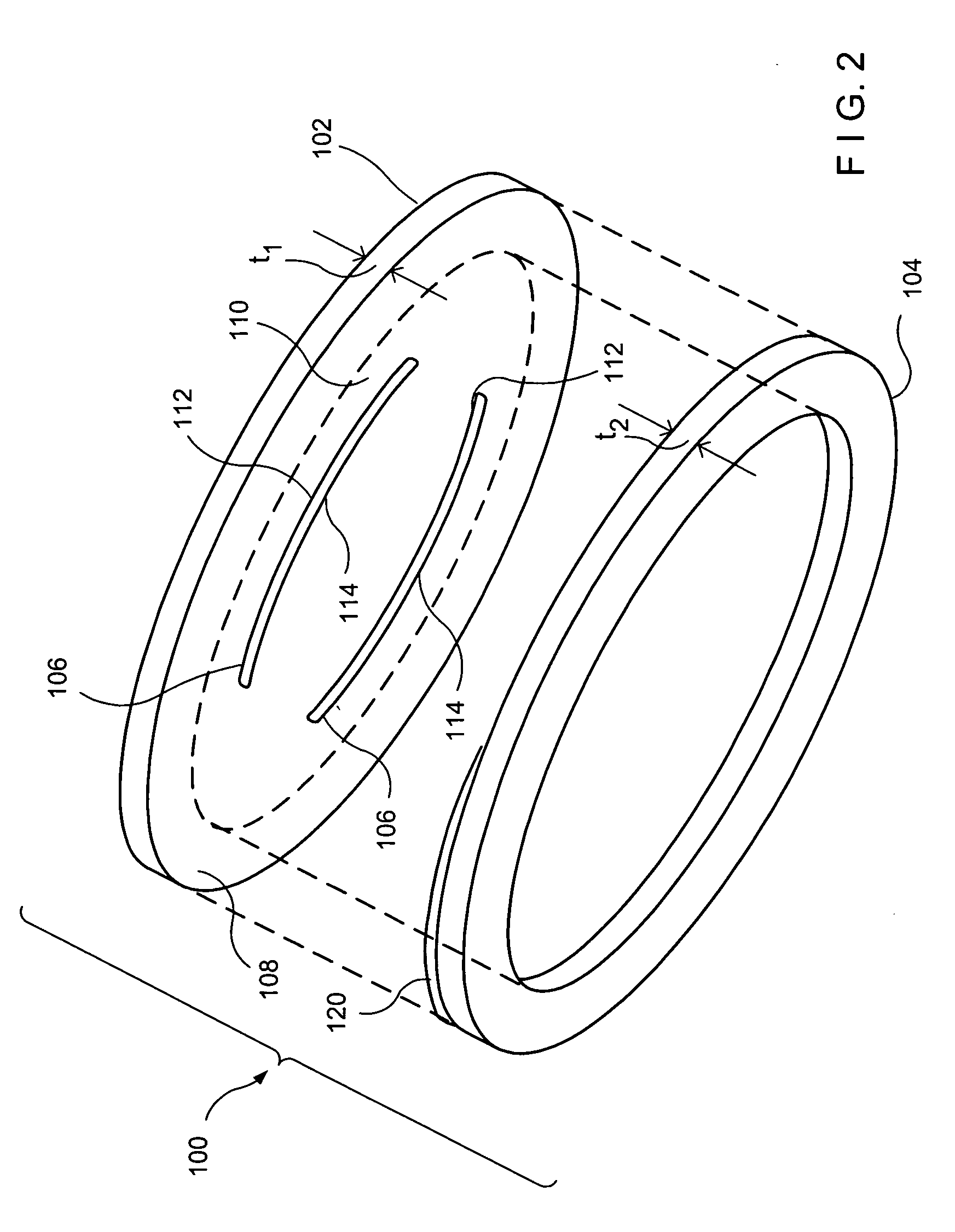
[0006] In one aspect, the present invention is directed to a pressure activated valve for medical applications comprising a housing having a lumen extending therethrough from a proximal end to a distal end thereof and a flow control membrane extending across the lumen to control flow therethrough, the flow control membrane including a mounting portion at which the flow control membrane is coupled to the housing and a lumen occluding portion having a slit extending therethrough so that, when the lumen occluding portion is subjected to a pressure of at least a predetermined threshold level, the lumen occluding portion moves from a closed configuration in which flow through the lumen is prevented to an open configuration in which flow is permitted and wherein a thickness of the mounting portion is greater

Problems solved by technology

It is impractical and dangerous to insert and remove the catheter for each dialysis session.
However, even small amounts of blood oozing into the proximal end of the catheter may be dangerous as thrombi can form therein due to coagulation.
This method is often unsatisfactory because the repeated application of the clamp may weaken the walls of the catheter due to the stress placed on the walls at a single point.
In addition,

Method used


Image

  • Stacked membrane for pressure actuated valve
  • Stacked membrane for pressure actuated valve
  • Stacked membrane for pressure actuated valve

Examples


Embodiment Construction

[0012] The present invention may be further understood with reference to the following description and the appended drawings, wherein like elements are referred to with the same reference numerals. The invention is related to the field of medical valves, and more specifically to the field of pressure activated valves that are used to seal a lumen of a medical catheter.

[0013] Semi-permanently placed catheters may be useful for a variety of medical procedures which require repeated access to a patient's vascular system in addition to the dialysis treatments mentioned above. For example, chemotherapy infusions may be repeated several times a week for extended periods of time. For safety reasons, as well as to improve the comfort of the patient, injections of these therapeutic agents may be better carried out with an implantable, semi-permanent vascular access catheter. Many other conditions that require chronic venous supply of therapeutic agents, nutrients, blood products or other fl...


PUM


Abstract

A pressure activated valve for medical applications comprises a housing having a lumen extending therethrough from a proximal end to a distal end thereof and a flow control membrane extending across the lumen to control flow therethrough, the flow control membrane including a mounting portion at which the flow control membrane is coupled to the housing and a lumen occluding portion having a slit extending therethrough so that, when the lumen occluding portion is subjected to a pressure of at least a predetermined threshold level, the lumen occluding portion moves from a closed configuration in which flow through the lumen is prevented to an open configuration in which flow is permitted and wherein a thickness of the mounting portion is greater than a thickness of the lumen occluding portion. A method of forming a membrane for a pressure activated valve, comprises the steps of forming a substantially planar flow control membrane dimensioned to fit in a housing of the pressure activated valve, wherein a mounting portion of the flow control membrane is adapted to engage the housing, and forming at least one slit in the flow control membrane, the slit being openable by pressure of a fluid in the pressure activated valve of at least a predetermined threshold level in combination with the steps of forming an annular base membrane dimensioned to substantially overlie the mounting portion of the flow control membrane and stacking the base membrane on the mounting portion of the flow control membrane.

Description

[0001] The present application incorporates by reference the entire disclosure of U.S. Application entitled “Pressure Activated Safety Valve With High Flow Slit” filed on even day herewith naming Karla Weaver and Paul DiCarlo as inventors, U.S. Application entitled “Pressure Activated Safety Valve With Anti-Adherent Coating” filed on even day herewith naming Karla Weaver and Paul DiCarlo as inventors, and U.S. Application entitled “Pressure Actuated Safety Valve With Spiral Flow Membrane” filed on even day herewith naming Paul DiCarlo and Karla Weaver as inventors, and U.S. Application entitled “Dual Well Port Device” filed on even day herewith naming Katie Daly, Kristian DiMatteo and Eric Houde as inventors. BACKGROUND OF THE INVENTION [0002] Many medical procedures require repeated and prolonged access to a patient's vascular system. For example, during dialysis treatment blood may be removed from the body for external filtering and purification, to make up for the inability of th...

Claims


Application Information

Patent Timeline
IPC IPC(8): A61M39/02A61M39/24F16K15/14F16K17/18
CPCA61M39/02A61M39/24F16K17/18A61M2039/2426F16K15/147A61M2039/242
Inventor WEAVER, KARLADICARLO, PAUL
Owner NAVILYST MEDICAL
Why Eureka
Try Eureka