Preliminary gas distributor for fluidized bed reactor

The technology of a gas pre-distributor and a fluidized bed reactor is applied in the improvement field of the fluidized bed reactor technology, and can solve the problems of unguaranteed gas flow uniformity, reduced inlet effect, large flow rate, etc. Reduced import effects, improved uniformity and stability

Inactive Publication Date: 2013-01-02
CHONGQING UNIV
View PDF4 Cites 1 Cited by
  • Summary
  • Abstract
  • Description
  • Claims
  • Application Information

AI Technical Summary

Problems solved by technology

[0005] The gas enters the pre-distributor through the pipe. Since the cross-section of the pipe at the inlet is often smaller than the cross-section of the gas pre-distributor, the fluid will not fill the cross-section immediately after entering, resulting in high flow velocity in some places and small flow velocity in some places, even there will be backflow
Existing gas predistributors have many structural forms, which can be roughly divided into two types: without guide plate and with guide plate, but most of them have the above-mentioned inlet effect problem, or reduce the inlet effect while making the air flow uniform not guaranteed

Method used


Image

  • Preliminary gas distributor for fluidized bed reactor
  • Preliminary gas distributor for fluidized bed reactor
  • Preliminary gas distributor for fluidized bed reactor

Examples


Embodiment 1

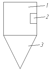
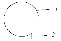
[0030] Such as figure 1 As shown, the gas pre-distributor of the fluidized bed reactor includes a gas inlet tangential to the gas pre-distributor and a conical structure below the pre-distributor. For a reactor with an inner diameter of 150mm, the optimized structure of the gas predistributor is selected: the gas inlet is rectangular, the length is 50mm, the width is 30mm, the ratio of length to width is 5:3, and the length and bed diameter (gas predistributor diameter) ratio of 1:3, the square inlet is located in the middle of the height of the pre-distributor. The conical structure is 150mm high and its height to bed diameter ratio is 1:1.

Embodiment 2

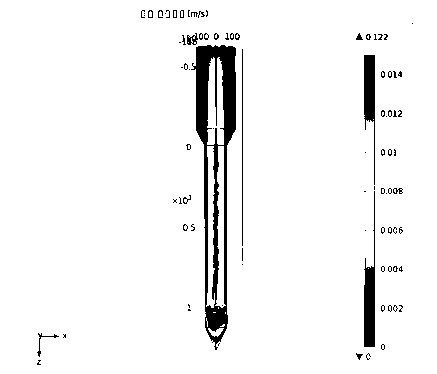
[0032] In a gas-solid fluidized bed reactor with a diameter of 1500 mm, air is used as the fluidizing gas, and the apparent operating gas velocity of the fluidized bed is 0.1 m / s, and the COMSOL simulation calculation software is used for simulation. The structural form of the gas pre-distributor is as follows: figure 1 , where the tangential square inlet is located in the middle of the height of the pre-distributor, the length is 500mm, and the width is 300mm; the height of the conical structure is 1500mm, and the diameter is 1500mm.

[0033] image 3 It is the velocity nephogram of the whole bed body of embodiment 2; Figure 4 Be embodiment 2 predistributor internal distribution plate lower surface cross-sectional velocity nephogram; Figure 5 It is the cloud diagram of the cross-sectional velocity on the upper surface of the distribution plate in Example 2. It can be seen from the figure that the gas velocity distribution in the whole bed is relatively uniform, all the ...


PUM


Abstract

The invention discloses a preliminary gas distributor for a fluidized bed reactor. The upper half part of the preliminary gas distributor is in a cylindrical structure, and the lower half part of the preliminary gas distributor is in a tapered structure; the cylindrical structure is provided with a gas inlet; and the gas inlet is arranged in the middle of the cylindrical structure and is arranged along the tangential direction of the side wall of the cylindrical structure. According to the preliminary gas distributor for the fluidized bed reactor disclosed by the invention, the gas inlet is arranged along the tangential direction of the preliminary gas distributor, and when gas is input, a spiral-flow-type planar flow field is formed below a distribution plate, so that the flow field of the gas is changed, the entrance effect of fluid is alleviated, the gas cannot directly impact the distribution plate to cause uneven distribution of gas flow, and the uniformity and stability of gas flow distribution in the fluidized bed can be improved. The preliminary gas distributor does not need a guide plate and is simple in structure and convenient for processing.

Description

technical field [0001] The invention relates to the improvement of fluidized bed reactor technology, in particular to a gas predistributor on the fluidized bed reactor. [0002] Background technique [0003] Due to its unique advantages, fluidized bed reactors, such as: enhanced heat and mass transfer between fluid and solid, uniform temperature field; enhanced heat transfer between bed and tube wall; can be transported in large quantities like fluid; easy to realize The continuity and automation of the process; solid particles can be used as a heat carrier, making it more and more widely used in many industrial fields. However, with the continuous development of industrial processes and the continuous expansion of equipment scale, the diameter of fluidized bed reactors continues to increase, so that the uniform distribution of gas in the fluidized bed has become one of the key issues in the design of fluidized beds in industry one. [0004] The fluidized bed gas pre-dist...

Claims


Application Information

Patent Timeline
Patent Type & Authority Applications(China)
IPC IPC(8): B01J8/24
Inventor 尹国亮温良英梁海龙
Owner CHONGQING UNIV
Why Eureka
Try Eureka