Intravenous delivery system

a technology of intravenous solution and delivery system, which is applied in the direction of filtering accessories, instruments, other medical devices, etc., can solve the problems of nosocomial infection, increased time for emptying of drip chamber, and reduced volum

Active Publication Date: 2005-08-04
BECTON DICKINSON & CO
View PDF44 Cites 102 Cited by
  • Summary
  • Abstract
  • Description
  • Claims
  • Application Information

AI Technical Summary

Benefits of technology

[0013] In accordance with one embodiment, a self-priming IV-solution delivery system is disclosed for intravenous delivery of a solution from a container to a patient when the container is disposed at a height above the patient. The delivery system includes a coupling assembly connected or in communication with the container to provide flow of the solution. A drip chamber having a bottom wall and a side wall is coupled to the coupling assembly to receive solution drops formed from the flow of the solution. The drops form a reservoir in the drip chamber. The side wall of the drip chamber includes an opening located at a height above the bottom wall, and a vent plug is provided for covering the opening. The vent plug allows air contained in the drip chamber which becomes displaced upon formation of the reservoir to escape from the drip chamber through the vent plug. A patient conduit is coupled to the drip chamber output and has a termination end attachable to an intravenous needle of the patient for receiving a flow of solution from the reservoir. The patient conduit includes a flow restriction device to restrict the flow of air and liquid in the patient conduit, thereby allowing the reservoir to attain a level at least equal to the height of the vent plug while air in the patient conduit is expelled from the termination end. Wetting of the vent plug by the reservoir prevents entry of air through the vent plug to the drip chamber and prevents the exit of solution from the drip chamber through the vent plug.
[0016] In accordance with another embodiment, a drip chamber is described for use in a self-priming IV-solution delivery system for intravenous delivery of a solution from a container to a patient. The delivery system includes a coupling assembly having an input and an output and configured, at its input, for coupling to the container to provide flow of the solution through the coupling assembly output. The delivery system also includes a patient conduit line for providing solution from the container to the patient. The drip chamber includes a top wall, a bottom wall, a side wall, an input and an output, and is coupled, at its input, to the coupling assembly output to receive solution drops formed from the flow of the solution for creating a reservoir defined between the bottom wall and side wall. The drip chamber side wall has an opening located at a height between the top wall and bottom wall, and a vent plug covering the opening. The vent plug allows air contained in the drip chamber which becomes displaced upon formation of the reservoir to escape from the drip chamber through the vent plug and prevents air from entering the drip chamber through the vent plug and medicament from exiting the drip chamber through the vent plug upon wetting of the vent plug by the reservoir.
[0018] According to another embodiment, an IV-solution delivery system is described having a coupling assembly configured for coupling to a container of solution to remove solution from the container, a patient conduit for providing the removed solution to a patient, and means for regulating a flow rate of solution from the coupling assembly to the patient conduit. The patient conduit is coupled at one end to the regulating means and has a termination end. A termination end cap is provided at the termination end of the patient conduit. The end cap has a vent for restricting the flow of solution into the patient conduit and allows air displaced by the flow of solution in the patient conduit to escape through the termination end. The end cap also includes a termination end vent plug for preventing the escape of solution through the termination end cap upon wetting of the vent plug by the solution.

Problems solved by technology

One problem with such a priming technique is that if the drip chamber is squeezed too hard such that an excessive amount of air is removed, the reduced volume will be filled by an excess amount of medicament.
The emptying of the drip chamber takes additional time and may increase the risk of line contamination that may result in a nosocomial infection to the patient.
This task is further complicated as a result of the direct connection between the drip chamber and the spike assembly.
Such direct connection provides little or no maneuverability of the drip chamber because such manipulation may cause a disturbance of the connection between the spike assembly and the medicament container.
Another problem with existing IV systems is that when the drip chamber is squeezed to adjust the solution flow rate, the pressurized conditions in the drip chamber cause the infused liquid to flow as a narrow stream into the drip chamber at a high velocity.
When this occurs, a time-consuming task must be performed to purge the air bubbles from the drip chamber and from the conduit leading to the patient.
If air bubbles are not purged, they may enter the patient and cause an embolism or other harmful effects.
These drawbacks reduce the efficiency in which IV systems can be connected to patients when, especially in emergency conditions, time may be of the essence.

Method used


Image

  • Intravenous delivery system
  • Intravenous delivery system
  • Intravenous delivery system

Examples


Embodiment Construction

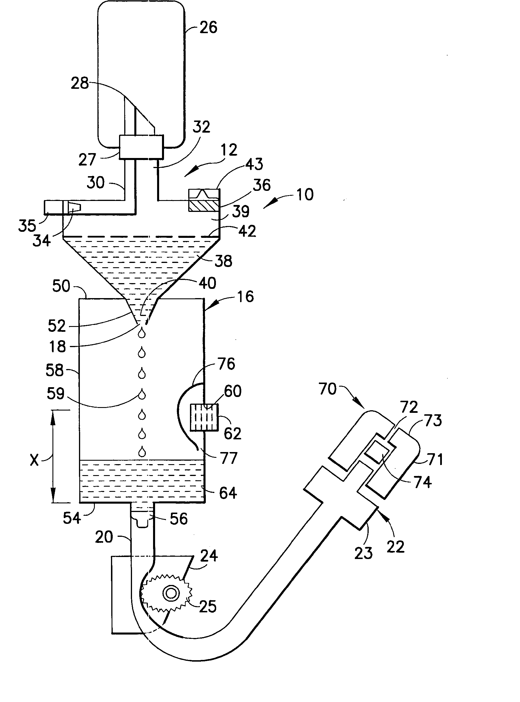
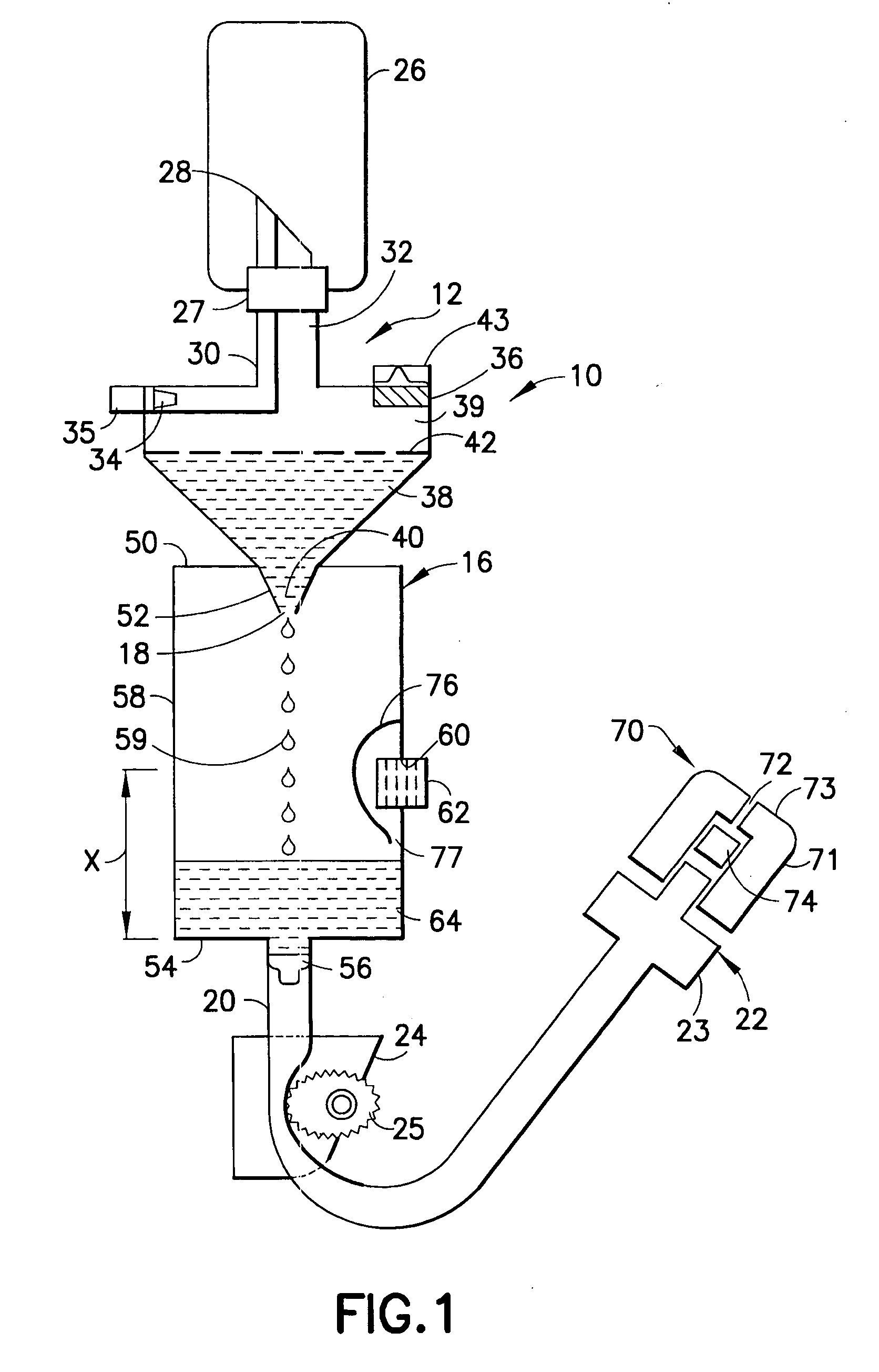
[0027]FIG. 1 depicts a self priming IV delivery system 10 used for administering a IV-solution through a vein of a patient. As used herein, the terms “IV-solution”, “solution” and “medicament” are intended to refer to any substance that may be administered intravenously to a patient. The solution is located in a container 26 such as a vented rigid container or bottle, or a collapsible plastic bag, as is known in the art. The IV system 10 is a hermetically sealed system and includes a solution coupling spike assembly 12 having a lancing or piercing member 28 for piercing a seal 27 on the container 26. Other primary components of the IV system 10 include a drip chamber 16, and a patient conduit or line 20 having a termination end 22 and supporting a flow controller such as a roller clamp 24 for controlling the flow of liquid medicament in the patient line 20.

[0028] Spike assembly 12 can be of various configurations as is well known to those of ordinary skill in the art. Preferably, t...


PUM


Abstract

An intravenous system includes an assembly for coupling a solution container to a delivery system drip chamber used for regulating the flow rate of solution in a patient intravenous line. In one embodiment, the solution delivery system includes a drip chamber having an opening formed in a side wall, and a vent plug disposed in the opening for providing a self-priming function to the IV system. A termination end of the patient intravenous line includes an end cap with a vent and a seal for allowing air in the intravenous line to escape through the end cap while preventing leakage of solution from the termination end.

Description

BACKGROUND OF THE INVENTION [0001] 1. Field of the Invention [0002] The present invention is directed to a system for delivering liquid to patients intravenously. More particularly, the present invention pertains to an intravenous solution delivery system having a self-priming drip chamber. The present invention is also directed to an intravenous delivery system having a venting end cap to allow air present in an intravenous line to be removed. [0003] 2. Description of the Related Art [0004] Medical liquid delivery systems are used by medical personnel to inject nutrients and / or medication into a patient's body. “Medical liquid delivery systems,” as used herein, include, for example, any system for delivering an intravenous solution such as glucose, saline solution, medical dyes, and medication in liquid form, to a patient. Such systems are used during surgery or when a patient is otherwise unable to ingest nutrients or medication orally. [0005] Intravenous liquid delivery systems (...

Claims


Application Information

Patent Timeline
Patent Type & Authority Applications(United States)
IPC IPC(8): A61M5/14A61M5/168A61M5/162A61M5/165A61M5/31A61M5/38A61M39/20A61M39/28
CPCA61M5/1411A61M5/162A61M5/385A61M39/20A61M39/285A61M2205/7536A61M2005/1623A61M2039/205A61M2205/7509A61M2205/7518A61M2005/1402
Inventor MINH MINER, TOMHARTL, PETERCHRISTOPH, ANGELIKA
Owner BECTON DICKINSON & CO
Why Eureka
Try Eureka