
Bridging apparatus and method for enabling a UPnP device to control a PLC device

Inactive Publication Date: 2005-08-04
SAMSUNG ELECTRONICS CO LTD
View PDF6 Cites 92 Cited by
  • Summary
  • Abstract
  • Description
  • Claims
  • Application Information

AI Technical Summary

Benefits of technology

[0009] The present invention provides an apparatus and method for effectively realizing a Power Line Control (PLC)-to-Universal Plug And Play (UPnP) bridge in such a manner that PLC devices can join a UPnP network while meeting a standard device specification defined by the UPnP.

Problems solved by technology

The conventional PLC technology has several problems.
One problem associated with use of a webpage-based UI is that it is possible to achieve a user-to-device control, but not a device-to-device control.
Another problem is that it is difficult to create an application for controlling a PLC device where other features are added.
Another problem with use of the webpage-based UI is that it requires the appropriate webpage address to be found and set, and it also allows only external devices with a web browser to control a PLC device.

Method used


Image

  • Bridging apparatus and method for enabling a UPnP device to control a PLC device
  • Bridging apparatus and method for enabling a UPnP device to control a PLC device
  • Bridging apparatus and method for enabling a UPnP device to control a PLC device

Examples


Embodiment Construction

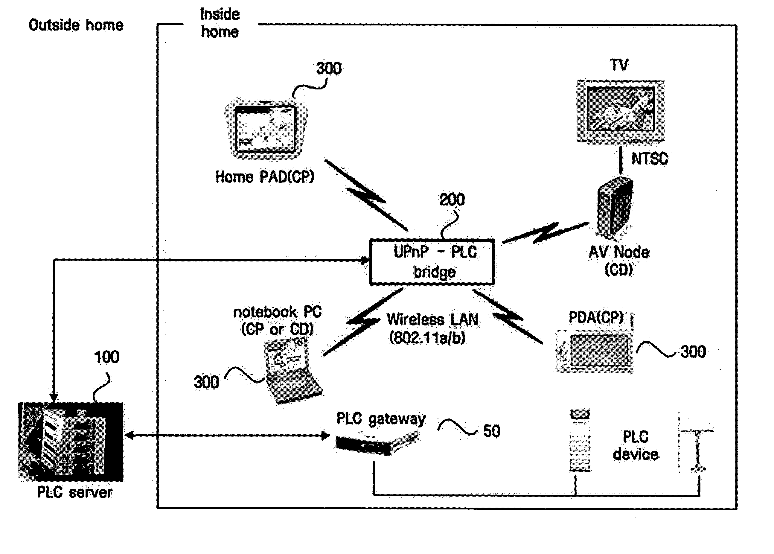
[0021] The present invention is intended to treat and control a Power Line Control (PLC) device on a conventional PLC network as if it were a Universal Plug And Play (UPnP) by integrating UPnP technology using ‘UPnP Device Architecture, Jun. 13, 2000, Version 1.0’ with a conventional PLC technology.

[0022] The invention will now be described more fully with reference to the accompanying drawings, in which exemplary embodiments of the invention are shown. This invention may, however, be embodied in many different forms and should not be construed as being limited to the embodiments set forth herein; rather, these embodiments are provided so that this disclosure will be thorough and complete, and will fully convey the concept of the invention to those skilled in the art. The spirit and scope of the invention is defined by the appended claims. In the drawings, the same reference numerals denote the same element.

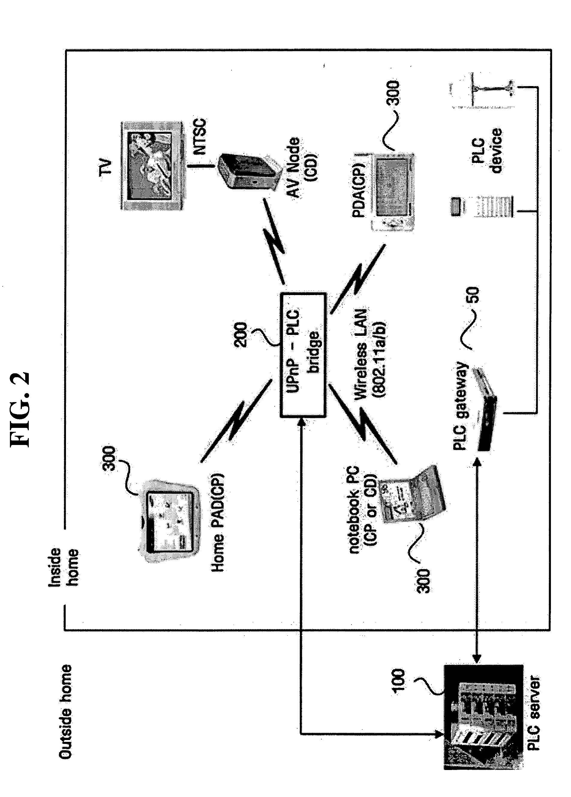
[0023]FIG. 2 shows the overall structure of a bridging apparatus according...


PUM


Abstract

Provided are an apparatus and method for enabling Power Line Control (PLC) devices to work like Universal Plug And Play (UPnP) devices by allowing the PLC devices to participate in a UPnP network. A bridging apparatus for enabling the UPnP device to control the PLC device includes a unit for generating a device description XML document for each device type using information on the PLC devices and transmitting the same document to a UPnP control point; a unit for, upon receipt of a control command from the control point, converting the control command into a control command conforming to a PLC protocol and transmitting the converted control command to a PLC device, and for, upon receipt of an information packet conforming to the PLC protocol from the PLC device, converting the packet to an event message conforming to a UPnP protocol and transmitting the event message to the control point.

Description

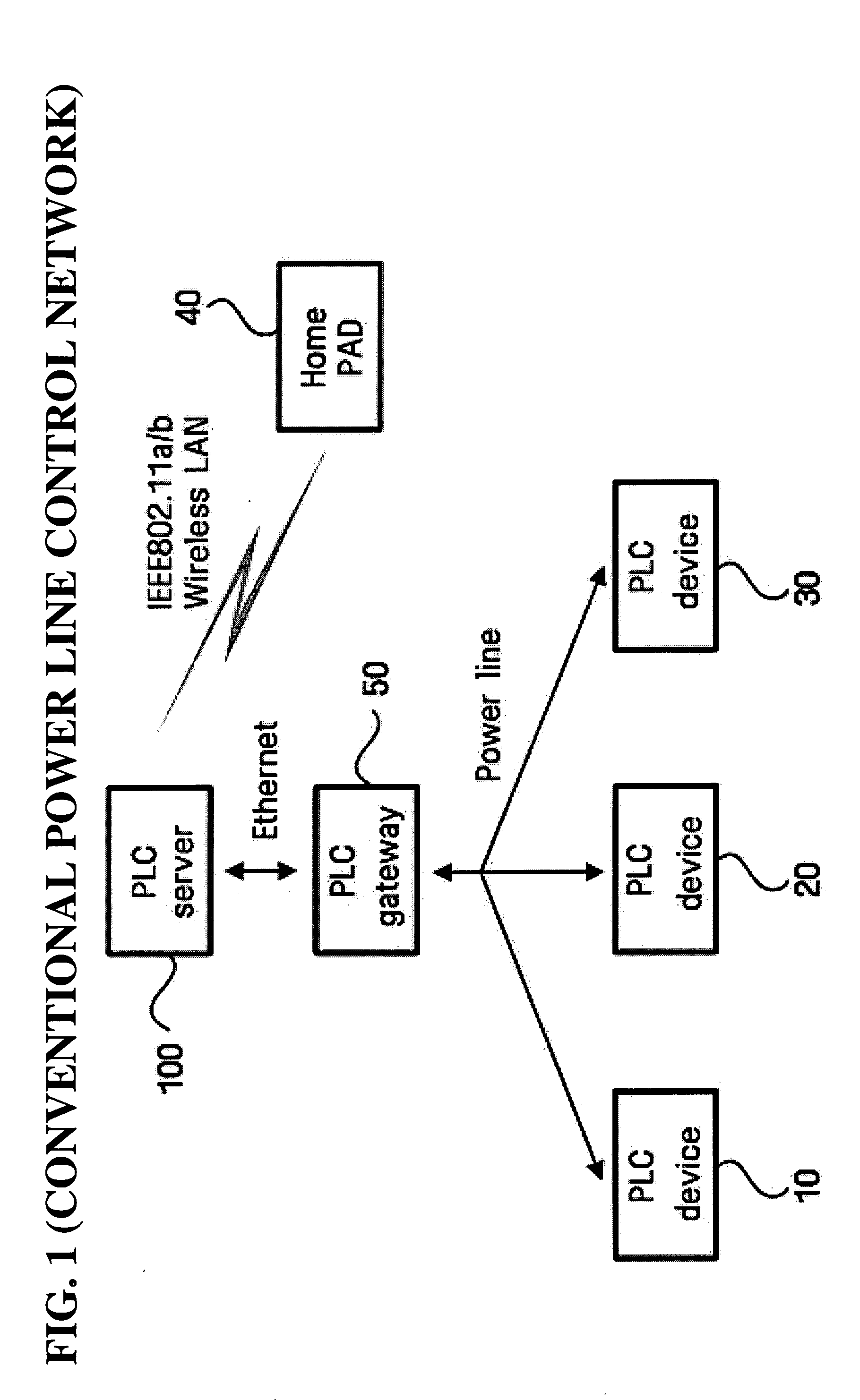
CROSS-REFERENCE TO RELATED APPLICATION [0001] This application claims the priority of Korean Patent Application No. 10-2004-0006670 filed on Feb. 2, 2004 in the Korean Intellectual Property Office, the disclosure of which is incorporated herein in its entirety by reference. BACKGROUND OF THE INVENTION [0002] 1. Field of the Invention [0003] The present invention relates to a method for enabling compatibility between Universal Plug And Play (UPnP) and Power Line Control (PLC) networks, and more particularly, to an apparatus and method for enabling a PLC device to work like a UPnP device by allowing the PLC device to participate in an UPnP network. [0004] 2. Description of the Related Art [0005]FIG. 1 shows the operation of a conventional PLC network. Referring to FIG. 1, PLC devices 10, 20, and 30 connect to a PLC gateway 50 via a power line, and the PLC gateway 50 connects to a PLC server through an Ethernet. A Home PAD 40 and other external devices for controlling the PLC devices 1...

Claims


Application Information

Patent Timeline
IPC IPC(8): H04L12/66G05B19/18H04L12/28
CPCH04L12/2803H04L12/2809H04L12/2812H04L2012/2849H04L12/2836H04L2012/2841H04L2012/2843H04L12/2832E01C5/08E01C9/086
Inventor AHN, JIN-YONG
Owner SAMSUNG ELECTRONICS CO LTD
Learn More