
X-ray sensitive battery separators and related methods

a battery separator and x-ray technology, applied in the direction of cell components, instruments, sustainable manufacturing/processing, etc., can solve problems such as shortening the internal space, and achieve the effects of easy manufacturing, easy detection, and x-ray sensitiv

Active Publication Date: 2011-07-21
CELGARD LLC
View PDF11 Cites 11 Cited by
  • Summary
  • Abstract
  • Description
  • Claims
  • Application Information

AI Technical Summary

Benefits of technology

[0013]In accordance with at least selected embodiments of the present invention, there are provided improved battery separators, methods, or the like, such as an improved battery separator which is x-ray sensitive or readily detectable when inserted or embedded in a battery, cell, stack, jellyroll, can, or the like, to determine its position within the battery, cell, stack, jellyroll, can, or the like, or to determine its position relative to the electrodes, which is relatively easy to manufacture, is low cost, meets performance requirements, meets product specifications, and / or the like. Furthermore, in accordance with at least selected embodiments of the present invention, there are provided improved methods for making, using, or detecting the position of a separator in a battery, cell, stack, jellyroll, can, or the like, such as an improved battery separator which is x-ray sensitive or readily detectable, to determine its position within the battery, cell, stack, jellyroll, can, or the like, or relative to the electrodes, which is relatively easy and cost effective, for manufacturing such a separator which is relatively simple and cost effective, for using such a separator which is relatively simple and cost effective, and / or the like.

Problems solved by technology

A battery separator is typically microporous to allow ionic current with least possible resistance while preventing the electrodes from direct contact resulting in an internal short.

Method used


Image

  • X-ray sensitive battery separators and related methods
  • X-ray sensitive battery separators and related methods

Examples


Embodiment Construction

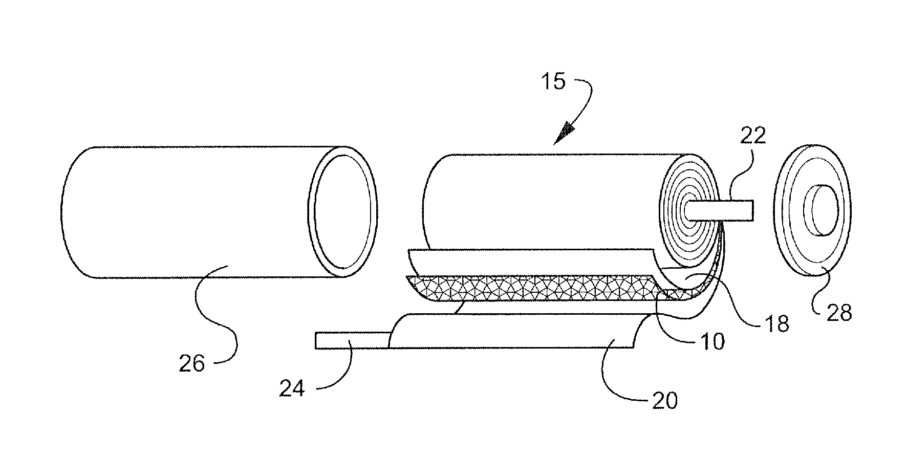
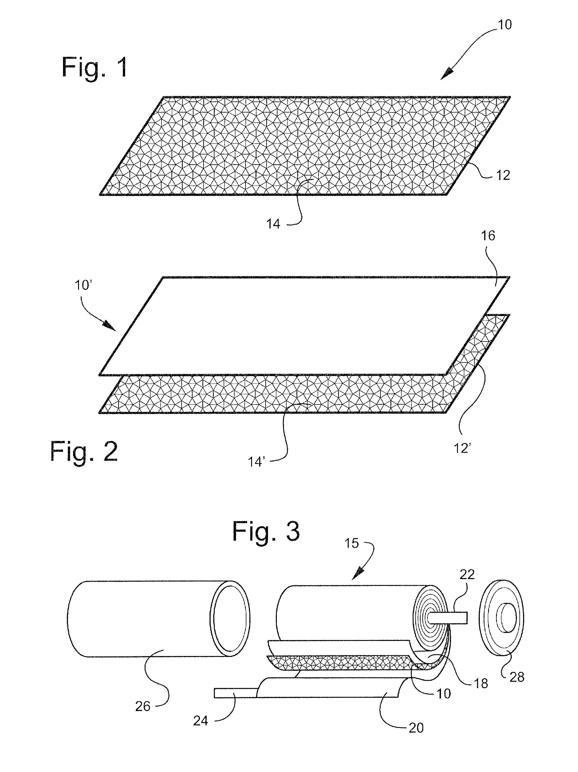
[0023]Referring to the drawings wherein like numerals indicate like elements, there is shown, in FIG. 1, a first embodiment of an X-ray sensitive battery separator 10. The X-ray sensitive battery separator 10 includes a microporous membrane 12, which contains an X-ray detectable element 14 dispersed therethrough.

[0024]Microporous membrane 12 may be any microporous membrane which contains X-ray detectable element 14. Microporous membranes are generally known in the art. Microporous membrane 12 may be made from any material, for example a polymer. A polymer, for example, may be any synthetic polymer, cellulose, or synthetically modified cellulose. The preferred synthetic polymers are polyolefins, e.g., polyethylene (PE), polypropylene (PP), polymethylpentene, polybutylene, ultra high molecular weight polyethylene, ultra high molecular weight polypropylene, copolymers thereof, and mixtures or blends thereof. Microporous membrane 12 may have any porosity; for example, microporous membra...


PUM

PropertyMeasurementUnit
weight %aaaaaaaaaa
weight %aaaaaaaaaa
weight %aaaaaaaaaa

Abstract

The instant application relates to an X-ray sensitive battery separator for a secondary lithium battery and a method for detecting the position of a separator in a secondary lithium battery. The X-ray sensitive battery separator includes a microporous membrane having an X-ray detectable element therein, thereon, or added thereto. The X-ray detectable element constitutes less than 20% by weight of the microporous membrane or separator. The method for detecting the position of a separator in a battery, cell, stack, jellyroll, can, or the like includes the following steps: (1) providing a battery, cell, stack, jellyroll, or the like including an X-ray sensitive battery separator; (2) subjecting the battery, cell, stack, jellyroll, or the like to X-ray radiation; and (3) thereby detecting the position of said separator in said battery, cell, stack, jellyroll, or the like.

Description

FIELD OF INVENTION[0001]The instant application relates to X-ray sensitive or detectable battery separators and methods for making and using such separators, including methods for detecting the position of such a separator in a battery, cell, stack, jellyroll, can, or the like.BACKGROUND OF THE INVENTION[0002]A battery separator is used to separate the positive and negative electrodes of a battery, for example, in a secondary lithium battery. A battery separator is typically microporous to allow ionic current with least possible resistance while preventing the electrodes from direct contact resulting in an internal short.[0003]In general, a battery separator is sandwiched between the positive electrode and the negative electrode of a secondary lithium battery. It is important for a battery separator to remain in its proper position because even a minute displacement may cause a short in the battery. Currently, other than as described in US Publication US2009 / 0081535 A1, published Ma...

Claims


Application Information

Patent Timeline
Patent Type & Authority Applications(United States)
IPC IPC(8): G01N23/18H01M2/14H01M2/16H01M2/02H01M50/431H01M50/449H01M50/457H01M50/491
CPCH01M2/1646Y02E60/122H01M10/4235H01M2/166H01M50/431H01M50/446H01M50/491H01M50/449H01M50/457G01N23/083Y02P70/50Y02E60/10H01M50/414H01M10/052
Inventor LI, XUEFAWENSLEY, C. GLENZHANG, ZHENGMING
Owner CELGARD LLC
Learn More