Field device electronics fed by an external electrical energy supply

a field device and electrical energy supply technology, applied in the direction of liquid/fluent solid measurement, volume measurement, electric variable regulation, etc., can solve the problem that the maximum released amount of energy is not sufficient to produce an ignition-capable spark, the current can be at least nominally dissipated or dissipated by the field device electronics, and the excess electrical energy can only be stored in very limited amounts

Active Publication Date: 2010-11-30
ENDRESS HAUSER FLOWTEC AG
View PDF13 Cites 11 Cited by
  • Summary
  • Abstract
  • Description
  • Claims
  • Application Information

AI Technical Summary

Benefits of technology

[0062]A further advantage of the invention is that the field device, because of the small power required for its operation, can, without more, meet the specifications of the various explosion-protection classes. This makes the field device specially suited also for application in those explosion-endangered areas, wherein only devices of intrinsic safety are allowed. Furthermore, the field device can, in such case, be so embodied, that it can work together with the usual field busses. This can, on the one hand, occur by direct connection to the field bus, e.g. corresponding to the FIELDBUS-protocol (FIELDBUS is a registered mark of the FIELDBUS-FOUNDATION). On the other hand, the working together can occur indirectly by means of a bus-coupler, e.g. corresponding to the so-called HART-protocol (HART is a registered mark of the HART User Group).
is that the field device, because of the small power required for its operation, can, without more, meet the specifications of the various explosion-protection classes. This makes the field device specially suited also for application in those explosion-endangered areas, wherein only devices of intrinsic safety are allowed. Furthermore, the field device can, in such case, be so embodied, that it can work together with the usual field busses. This can, on the one hand, occur by direct connection to the field bus, e.g. corresponding to the FIELDBUS-protocol (FIELDBUS is a registered mark of the FIELDBUS-FOUNDATION). On the other hand, the working together can occur indirectly by means of a bus-coupler, e.g. corresponding to the so-called HART-protocol (HART is a registered mark of the HART User Group).

Problems solved by technology

These three limit values are so selected that, in the case of malfunction, or in the case of a short circuit, the maximally released amount of energy is not sufficient to produce an ignition-capable spark.
As a result of this, a special problem of such two-wire field devices is that the electric power at least nominally dissipatable or to be dissipated by the field-device electronics—in the following referenced in short as “available power”—can fluctuate during operation in practically unpredictable manner over a wide range.
On the one hand, due to the intrinsic explosion safety often required for such two-wire measuring devices, at best, existing excess electrical energy can be stored in only very limited amounts internally in the field-device electronics.
Due to the highly accurate amplitude and frequency control of the exciter mechanism driving signal required for the operation of such a measurement pickup, unavoidable, for one thing, is a timewise high-resolution sampling of the measuring tube oscillations.
Further studies in this connection have, however, additionally shown that, because of the usually limited storage capacity for electric power, even a buffering of excess energy in the field device scarcely leads to any significant improvement of the signal-to-noise ratio dependent on the amplitude of the measuring tube oscillations.
In this respect, even a temporary and partial switching-off of the operating and evaluating circuit is little suited for two-wire measuring devices with active measurement pickup of the described kind, especially for two-wire measuring devices having a vibration-type measurement pickup involving the conveyance of flowing media.
However, a disadvantage of this field-device electronics is that all internal consumers are supplied practically from one and the same internal useful voltage and a possible collapse of this single useful voltage, for instance because of too little supply current, can lead to a state in which normal operation of the field device is no longer possible, or even to an abrupt, temporary, total stoppage of the field-device electronics.

Method used


Image

  • Field device electronics fed by an external electrical energy supply
  • Field device electronics fed by an external electrical energy supply
  • Field device electronics fed by an external electrical energy supply

Examples


Embodiment Construction

[0072]While the invention is susceptible to various modifications and alternative forms, exemplary embodiments thereof have been shown by way of example in the drawings and will herein be described in detail. It should be understood, however, that there is no intent to limit the invention to the particular forms disclosed, but on the contrary, the intention is to cover all modifications, equivalents, and alternatives falling within the spirit and scope of the invention as defined by the intended claims.

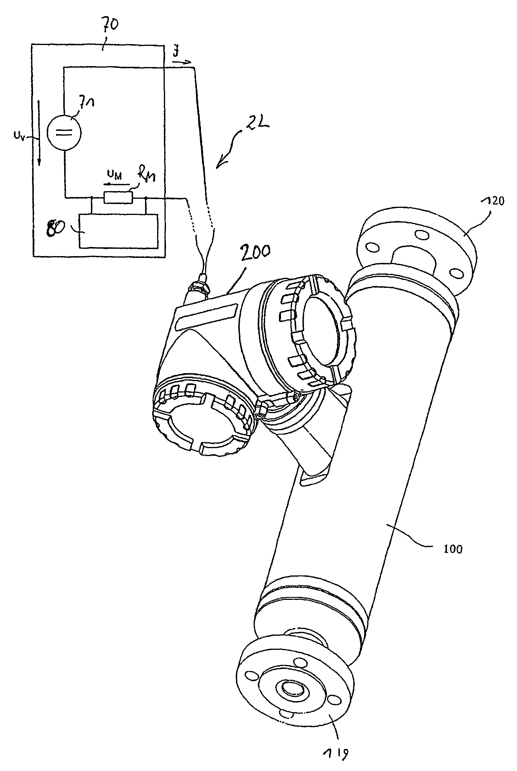
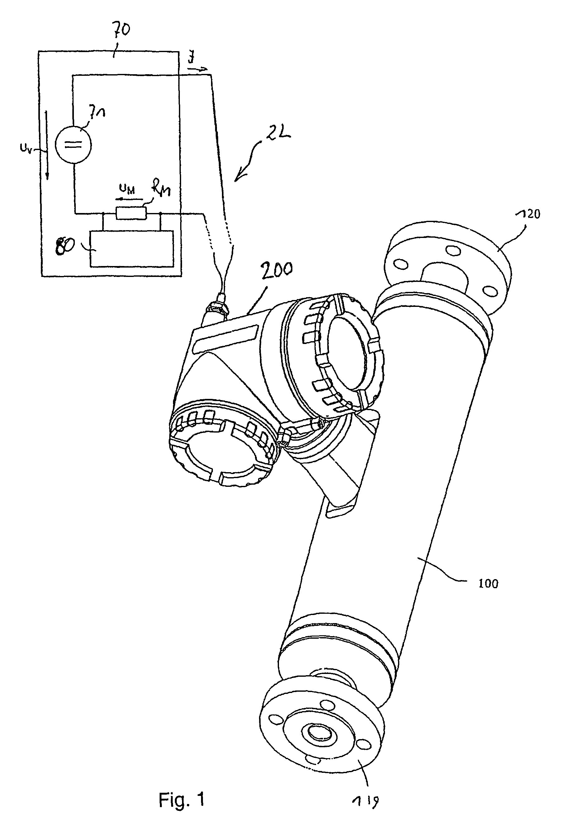
[0073]FIG. 1 shows an example of a field device suited for application in industrial measuring and automation technology, along with a field-device electronics 20 fed from an external, electrical energy supply 70. In operation, the external, electrical energy supply 70 provides an, especially unipolar, supply voltage UV and delivers in accompaniment therewith a variable, especially binary, supply current I correspondingly driven by the supply voltage UV. For this purpose, the field-de...


PUM


Abstract

The field-device electronics includes an electric current adjuster, through which a supply current flows, driven by a supply voltage provided by the external energy supply and adjusted by the current adjuster. Additionally, the field-device electronics includes an internal operating and evaluating circuit for controlling the field device, as well as an internal supply circuit feeding the internal operating and evaluating circuit. Provided in the supply circuit is a first useful-voltage controller flowed-through by a first component of the supply current, and a second useful-voltage controller flowed through, at least at times, by a second current component of the supply current, and providing in the field-device electronics a second internal, useful voltage. Further, the two useful-voltage controllers are galvanically separated from one another.

Description

CROSS-REFERENCES[0001]This application is a non-provisional application of U.S. Provisional application 60 / 818,270 filed on Jul. 5, 2006 and U.S. Provisional Application 60 / 818,331 filed on Jul. 5, 2006, and which claims the benefit of German application numbers 10 2006 030963.4 filed on Jul. 3, 2006 and 10 2006 030962.6 filed on Jul. 3, 2006.[0002]It also contains subject matter which is related to the subject matter disclosed in U.S. patent application Ser. No 11 / 822,180 filed on Jul. 3, 2007.FIELD OF THE INVENTION[0003]The invention relates to a field-device electronics for a field device. The field-device electronics is fed by an external electrical energy, or power, supply. The invention relates, as well, to a field device having such a field-device electronics.BACKGROUND OF THE INVENTION[0004]In the technology of industrial process measurements and automation, especially also in connection with the automation of chemical or technical-method processes and / or the control of indu...

Claims


Application Information

Patent Timeline
Patent Type & Authority Patents(United States)
IPC IPC(8): G01R27/00
CPCG01F1/8409G01F1/8413G01F1/8418G01F1/8422G01F1/8431G01F1/8436G01F1/849G01F15/024
Inventor LALLA, ROBERT
Owner ENDRESS HAUSER FLOWTEC AG
Why Eureka
Try Eureka