Elastic assembly floor plan design tool

a technology of elastic assembly and floor plan, applied in the direction of instruments, digital computers, computing, etc., can solve the problems of unsatisfactory wiring congestion in the circuit, too long wiring connections, etc., and achieve the effect of efficient positioning or assembling the components

Inactive Publication Date: 2005-08-04
MENTOR GRAPHICS CORP
View PDF3 Cites 45 Cited by
  • Summary
  • Abstract
  • Description
  • Claims
  • Application Information

AI Technical Summary

Benefits of technology

[0013] Various embodiments of the invention provide a tool that a designer may employ to more efficiently position or assemble the components of a circuit. More particularly, various examples of the invention provide a tool with a user interface that displays the global placement of blocks in a floor plan design, and the global routing of wires among the blocks. When the designer moves the placement of a block, the user interface responds by showing how various features of the circuit will change as a result of the move. For example, the user interface may show that moving one block closer to another block will create undesired wiring congestion in the circuit. The user interface also may show when moving a block will result in wiring connections that are too long to maintain a desired voltage level. With various embodiments of the invention, the tool may also automatically move the placement of related blocks as a group, so that various attributes, such as a minimum distance between adjacent blocks, are maintained.

Problems solved by technology

For example, the user interface may show that moving one block closer to another block will create undesired wiring congestion in the circuit.
The user interface also may show when moving a block will result in wiring connections that are too long to maintain a desired voltage level.

Method used


Image

  • Elastic assembly floor plan design tool
  • Elastic assembly floor plan design tool
  • Elastic assembly floor plan design tool

Examples


Embodiment Construction

Overview

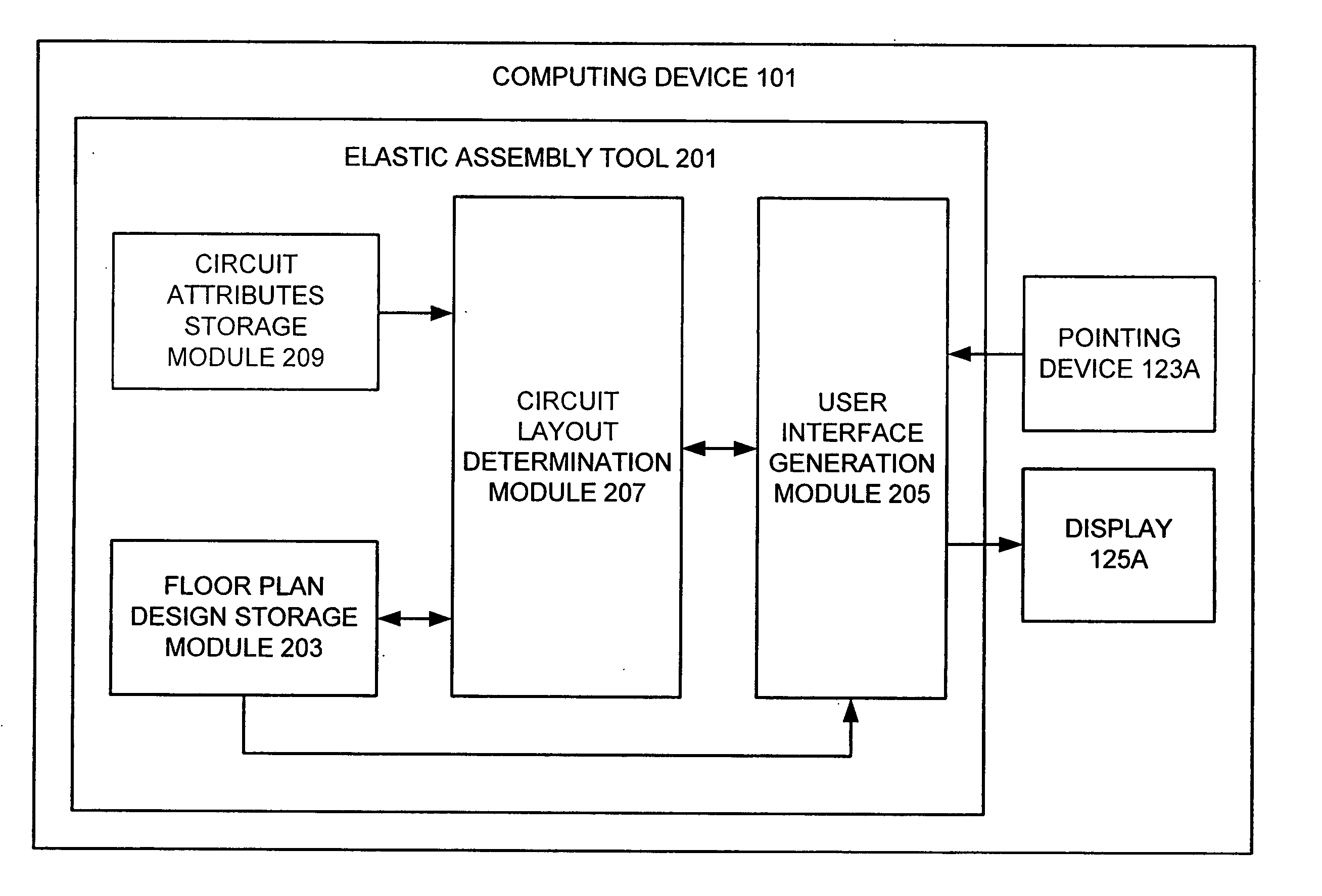
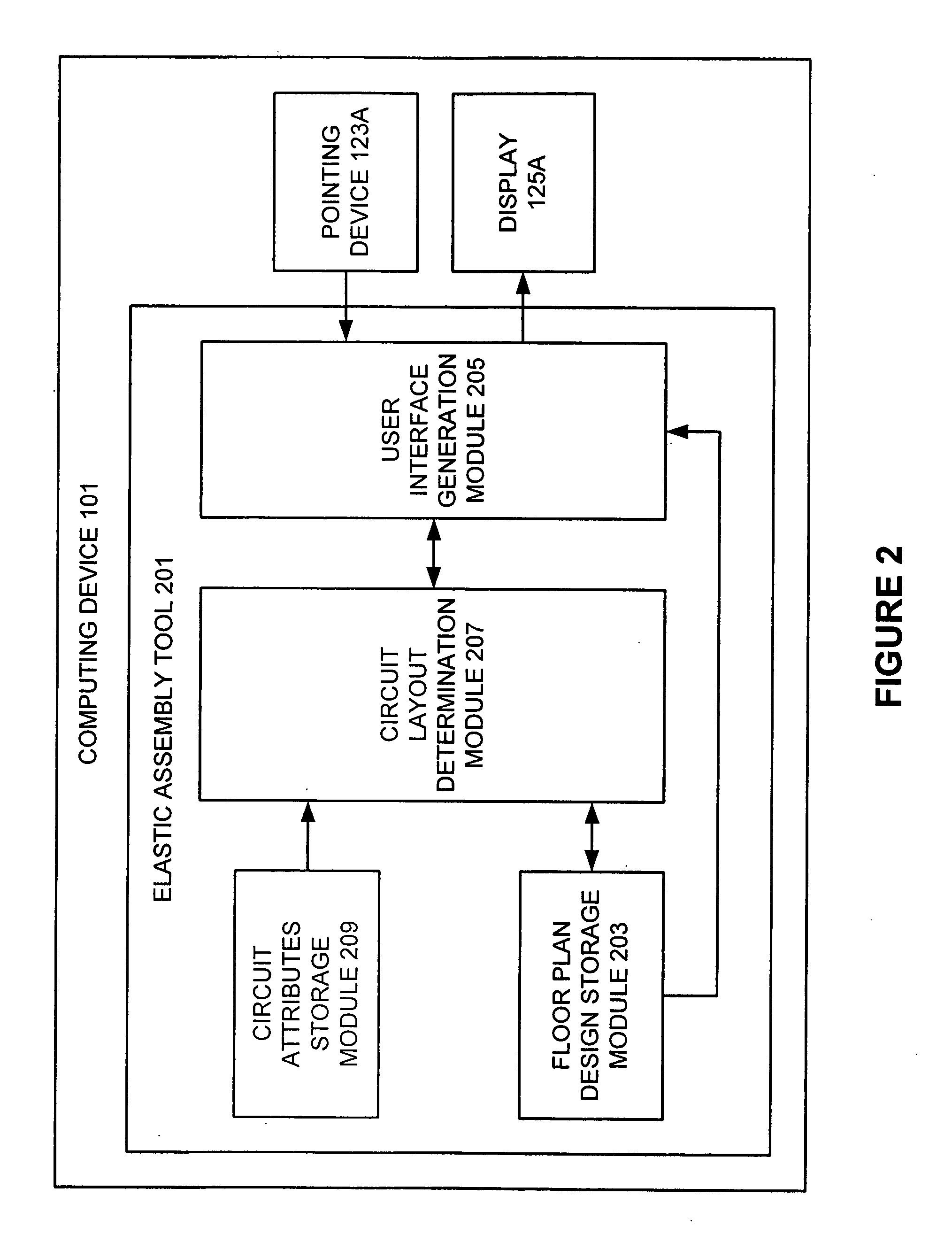
[0023] Various embodiments of the invention provide a floor planning tool that allows a designer to easily position components of a microcircuit in a floor plan design, while maintaining desired attributes for the design. More particularly, different embodiments of the invention provide a designer with a user interface that can display the floor plan of a design for a microcircuit. As used herein, the term “block” refers to the representation in a floor plan design of any group of circuit elements in a microcircuit design that may be repositioned, added, deleted or otherwise manipulated as a group. By using a pointing device, such as a keyboard, mouse, stylus, touchpad, joystick or the like, a circuit designer can select and move the placement of one or more of the blocks making up the floor plan design. As the designer moves a selected “target” block, the user interface graphically displays the various changes in the circuit characteristics and design that will result fro...


PUM


Abstract

A tool that a user may employ to assemble the components of a circuit in a floor plan design. The tool provides a user interface that displays the placement of blocks in a floor plan design, and the routing of wires among the blocks. When the designer moves the placement of a target block, the user interface automatically moves any adjacent blocks that would impede the movement of the target block and any block that would impede a block moved in response to the movement of the target block. The user interface may also respond to movement of a target block by showing how various features of the circuit will change as a result of the move. Thus, the user interface may show that moving one block closer to another block will create undesired wiring congestion in the circuit. The user interface also may show when moving a block will result in wiring connections that are too long to maintain a desired voltage level. The tool may also automatically move the placement of related blocks as a group, so that various attributes, such as a minimum distance between adjacent blocks, are maintained.

Description

RELATED APPLICATIONS [0001] This application is a continuation-in-part application of U.S. Provisional Patent Application No. 60 / 517,358, entitled “Elastic Assembly Tool, filed on Nov. 2, 2003, and naming Chih-Liang Cheng et al. as inventors, which application is incorporated entirely herein by reference. This application also claims priority to U.S. Provisional Patent Application No. 60 / 612,877, entitled “Chip Level Power / Ground Network Optimization Methodology,” filed on Sep. 24, 2004, and naming Ta-Cheng Lin et al. as inventors, which application is incorporated entirely herein by reference. Still further, this application claims priority to U.S. Provisional Patent Application No. 60 / 612,878, entitled “3D Viewing / Editing System,” filed on Sep. 24, 2004, and naming Yan Lin et al. as inventors, which application is incorporated entirely herein by reference.FIELD OF THE INVENTION [0002] The present invention relates to the design of microdevices. Various aspects of the present inven...

Claims


Application Information

Patent Timeline
Patent Type & Authority Applications(United States)
IPC IPC(8): G06F17/50
CPCG06F17/5072G06F30/392
Inventor CHENG, CHIH-LIANGYANG, CHUNG-DOLIN, YANLIAO, KUO-FENG
Owner MENTOR GRAPHICS CORP
Why Eureka
Try Eureka