Adiabatic power generating system
a power generation system and adiabatic technology, applied in the direction of machines/engines, combination engines, lighting and heating apparatus, etc., can solve the problems of short term ultimate yield, bearing and other moving parts are subject to short term high temperature yield stress, and turbines have a very high power to weight ratio but not good for partial loads
- Summary
- Abstract
- Description
- Claims
- Application Information
AI Technical Summary
Problems solved by technology
Method used
Image
Examples
embodiment one
Preferred Embodiment One
Gas Reactor Engine System
[0058] This embodiment is preferably a power plant for a self-propelled vehicle.
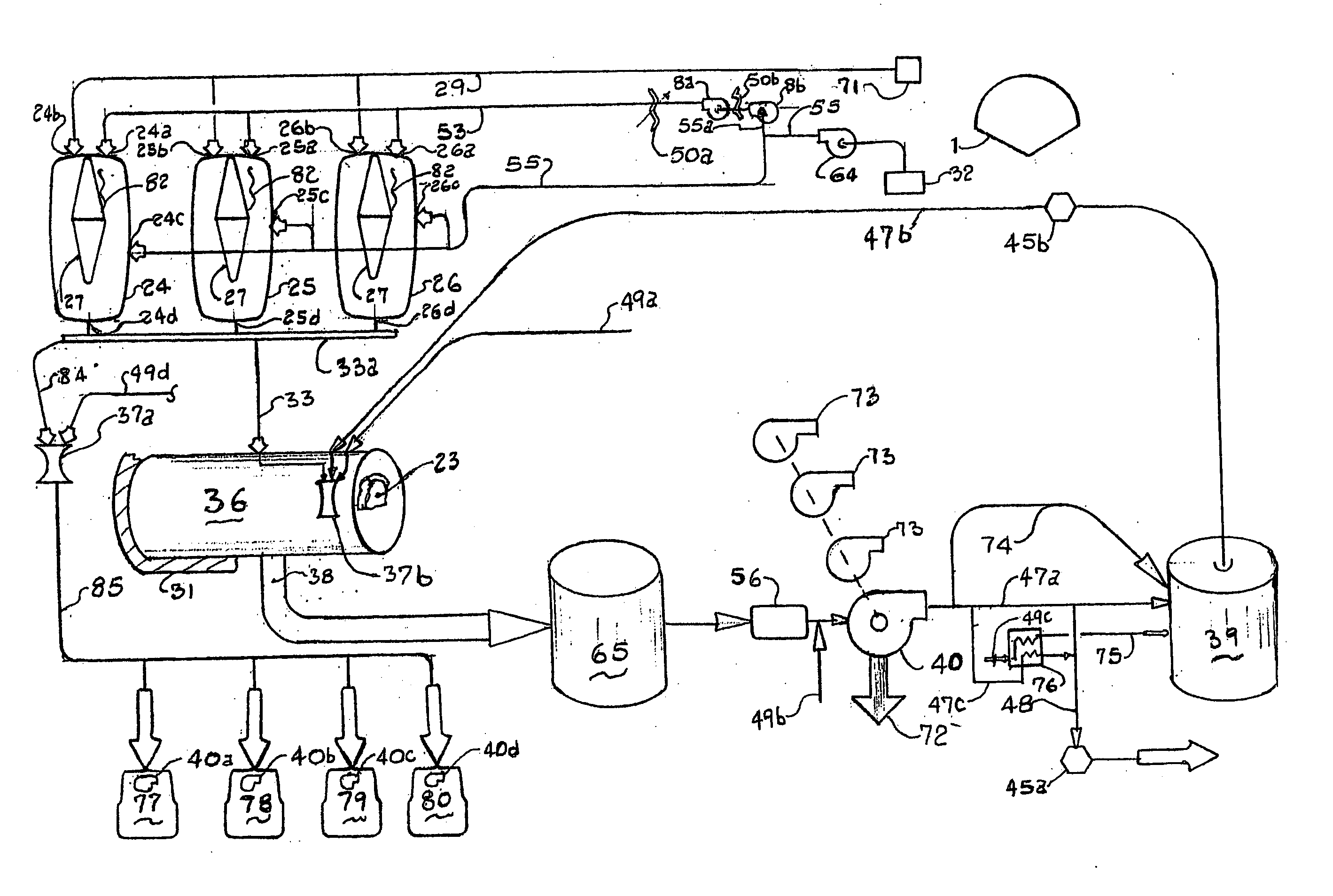
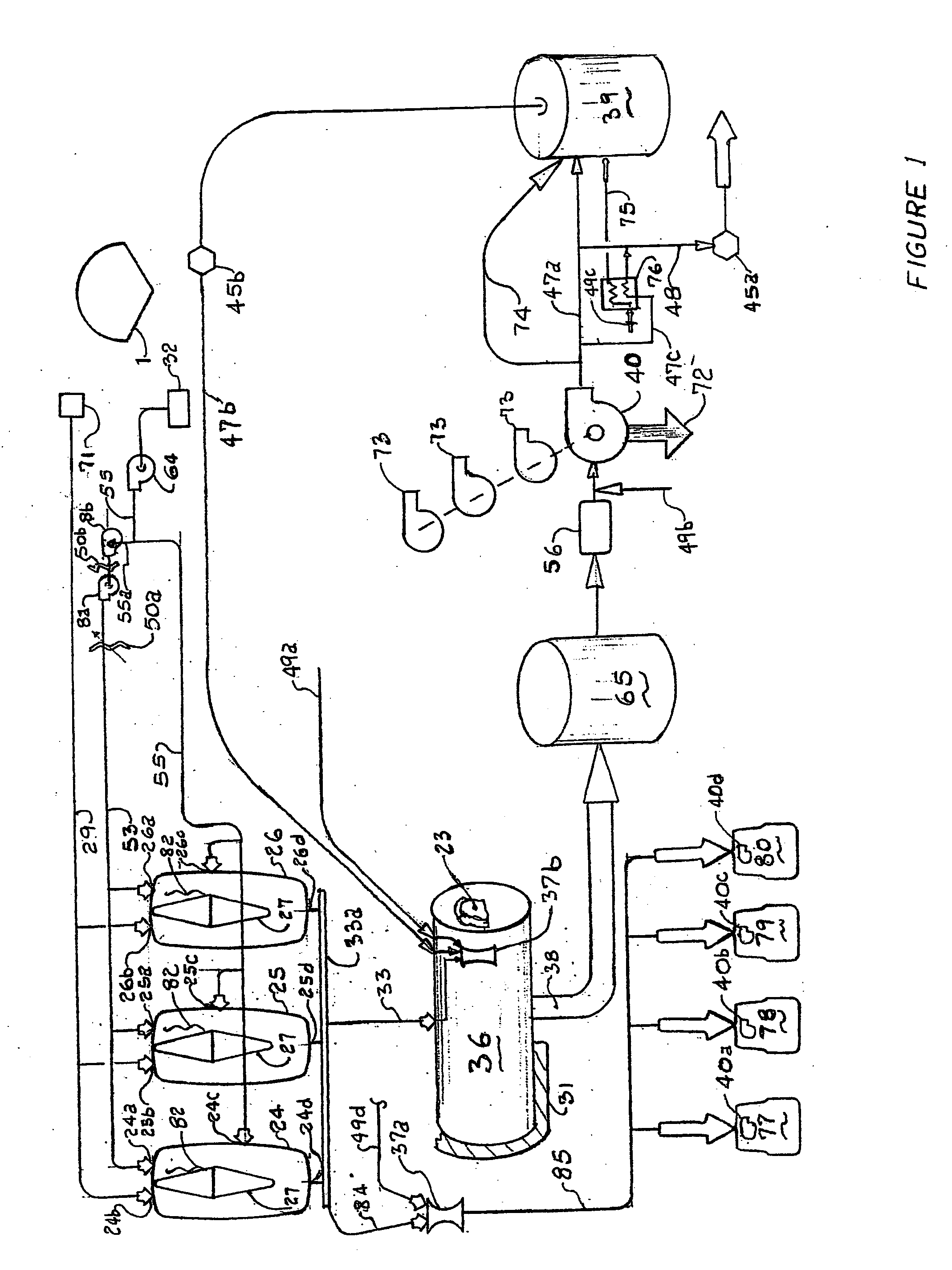
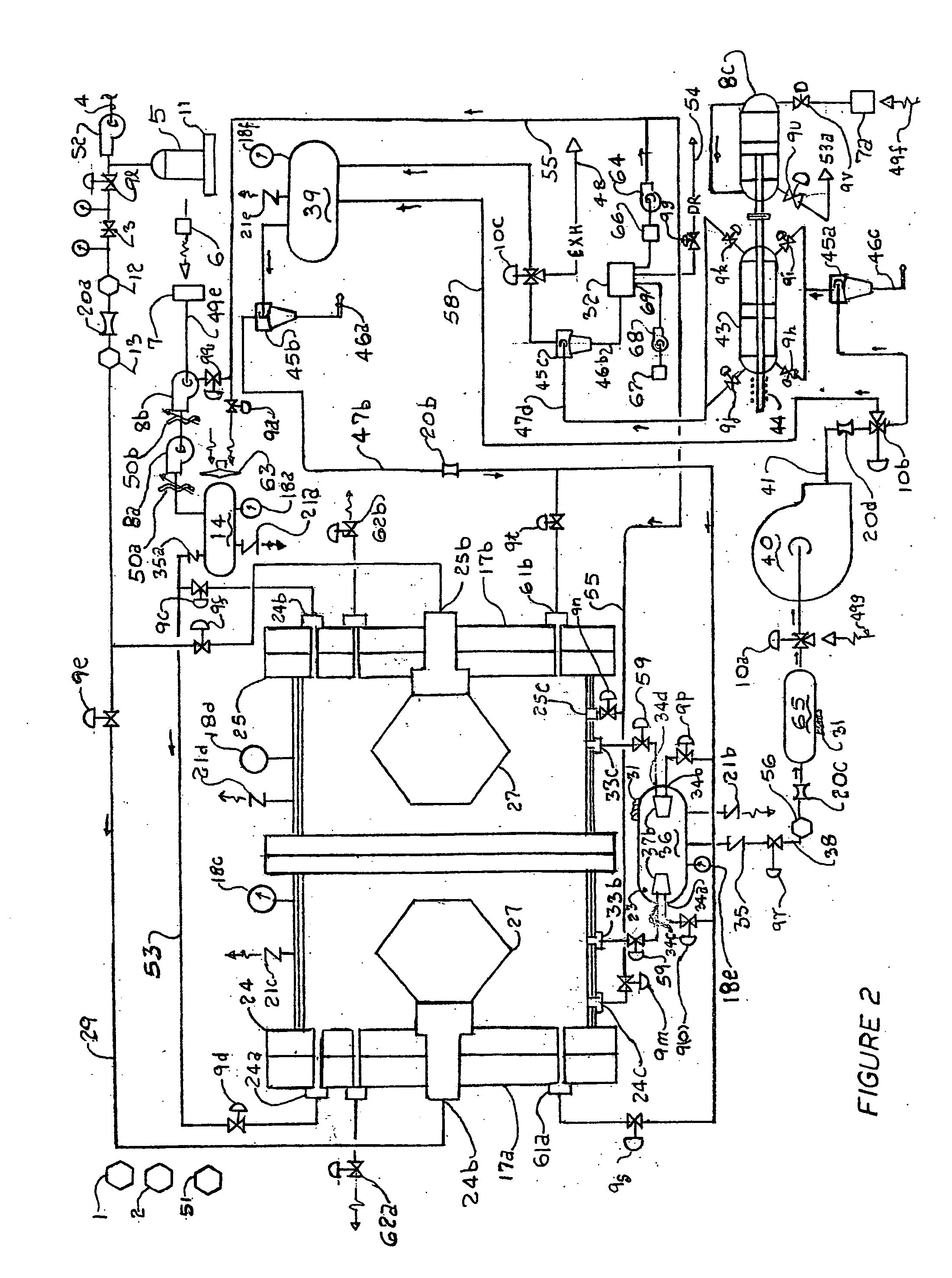
[0059] With reference to FIG. 2 and 3 and 4, the system depicted represents a design of a 220 HP output using compressed natural gas as the fuel. The expected indicated efficiency is 85% and brake efficiency is 79%. Two Gas Reactors, 24 and 25 operate in sequence so that there is a continuous flow of products of combustion. There are many variations to the composition of natural gas. This embodiment is presented as burning 100% Methane. The system is programmed for monitoring and automatic control with a suitable computer 1 and master timer 51 with provisions for manual and override controls. The useful work output of the gas motors is electrical or mechanical. Electrical energy is stored in a bank of batteries, 2. The process of operation is described below.
[0060] Ambient air at 60° F. and 50% relative humidity passes through air intake 6 and filter 7 ...
embodiment two
Preferred Embodiment Two
Ethanol for Self-Propelled Power Plant
[0068] Generally this embodiment is the same as Embodiment One. Ambient air and compressed air conditions are generally the same. Each gas reactor cavity is four cubic feet to provide adequate mass of air and products of combustion to lower reactor temperatures. In this Embodiment the thermal compression engine operates by burning ethanol containing 95% fuel and approximately 5% water including denaturing agents. A state of the art fuel injection system is installed to operate the gas reactor on a variant timed cycle initially set at seven seconds. Reactor Gas temperature is approximately 2100° F. and pressure is 736 PSIA. Water is injected into the air compressor at 0.6046 pounds of water per minute. There is enough water in the system produced by combustion and water contained in the fuel—little or no water injection is required. Fuel flow rate is 0.8915 pounds per minute
[0069] Thermal efficiency is expected to be 85%...
embodiment three
Preferred Embodiment Three
Fuel is Ethanol for Stationary Power Plant
[0070] This embodiment is suitable for larger plants for utility systems. This embodiment represents a One Megawatts module. The gas reactor is charged with 25 cubic feet compressed air at 125 PSIA. About 3.67 pounds of water per minute based on 0.726 pounds of water entrained by ambient air is charged into air compressors to absorb heat of compression by evaporation to facilitate isothermal compression. The fuel contains ninety five percent Ethanol and about 5% water. The fuel rate is about seven pounds per minute. The Molecular Weight of products of combustion is estimated at 28.32 pounds per pound mole and is close to that of air. The concentration of pollutants in atmospheric emissions is estimated to be traces of Hydrocarbons, Carbon Monoxide and Oxides of Nitrogen and less than 2 percent Carbon Dioxide. The Overall thermal efficiency is expected to be eighty nine percent and brake efficiency is expected to be...
PUM
 Abstract
Description
Claims
Application Information
 - R&D
- Intellectual Property
- Life Sciences
- Materials
- Tech Scout
- Unparalleled Data Quality
- Higher Quality Content
- 60% Fewer Hallucinations
Browse by: Latest US Patents, China's latest patents, Technical Efficacy Thesaurus, Application Domain, Technology Topic, Popular Technical Reports.
© 2025 PatSnap. All rights reserved.Legal|Privacy policy|Modern Slavery Act Transparency Statement|Sitemap|About US| Contact US: help@patsnap.com


