Pressure sensor assembly suitable for use in harsh environments

a technology of pressure sensor and assembly, which is applied in the field of pressure sensors, can solve the problems of large error in the attachment of the sensing element to the elastic structure, dc shift or drift error in the sensor signal, and difficulty in achieving true zero base strain sensitivity if not impossibl

Active Publication Date: 2005-08-11
WEATHERFORD TECH HLDG LLC
View PDF9 Cites 48 Cited by
  • Summary
  • Abstract
  • Description
  • Claims
  • Application Information

AI Technical Summary

Benefits of technology

[0011] A sensor for sensing the pressure of a first fluid is provided. In one embodiment, sensor for sensing the pressure of a first fluid includes a fiber optic based sensing element disposed in a housing. A buffer fluid is disposed in the housing and is in fluid communication with the sensing element. A pressure transmitter is coupled...

Problems solved by technology

It is also known that the attachment of the sensing element to the elastic structure can be a large source of error if the attachment is not highly stable.
A major source of such long term sensor instability is a phenomenon known as “creep”, i.e., change in strain on the sensing element with no change in applied load on the elastic structure, which results in a DC shift or drift error in the sensor signal.
It is further known that most attachments transmit a base strain to the sensor through the attachment structure and that a true zero base strain sensitivity is difficult if not impossible to achieve.
A disadvantage of such sensors is that th...

Method used


Image

  • Pressure sensor assembly suitable for use in harsh environments
  • Pressure sensor assembly suitable for use in harsh environments
  • Pressure sensor assembly suitable for use in harsh environments

Examples


Embodiment Construction

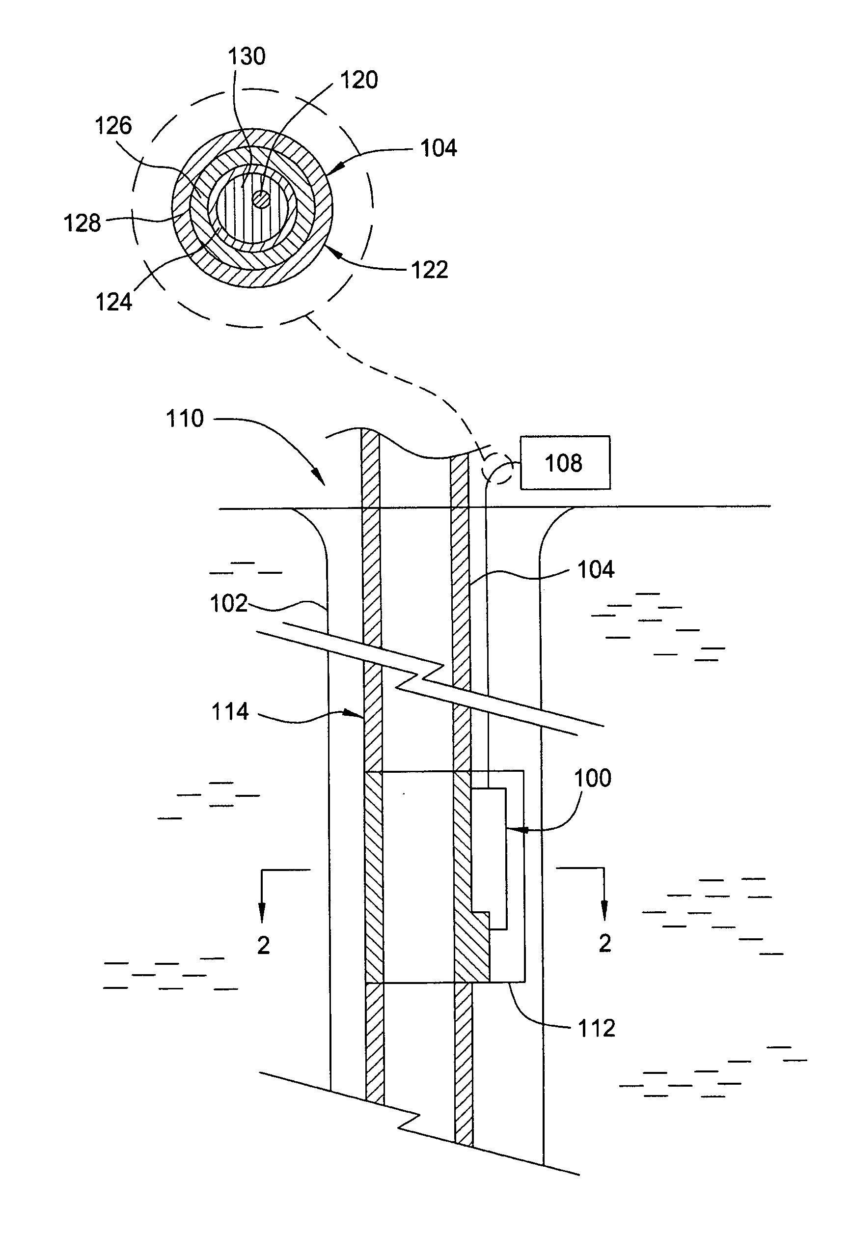
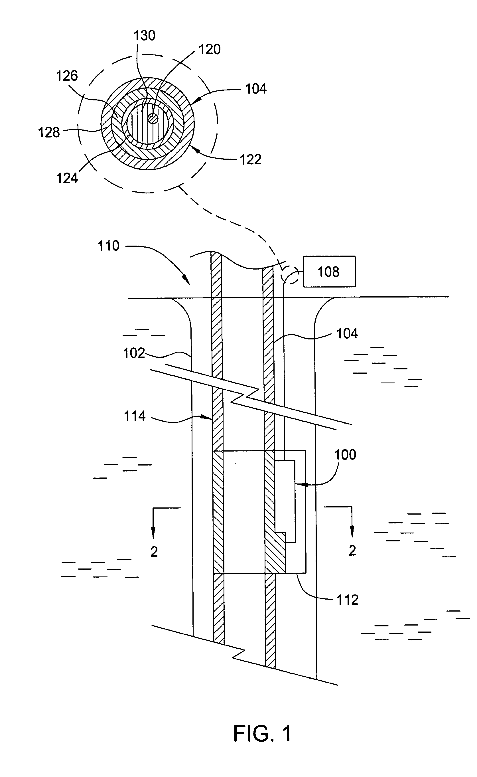
[0035]FIG. 1 is a simplified sectional view of an oil and / or gas well 110 having one embodiment of a pressure sensor 100 of the present invention disposed down the bore 102 of the well 110. The pressure sensor 100 is generally coupled by an optical cable 104 to a controller 108. The controller 108 is suitable for generating an optical signal transmitted through the cable 104 to the sensor 100 and resolving optical data reflected back through the cable 104 from the sensor 100. As is known, information from the transmitted and reflected signals may be utilized to determine pressure and / or other environmental information, such as shock, temperature, strain and the like, at the sensor 100. Suitable optical cables and controllers are available from Weatherford, Inc. located in Houston, Tex.

[0036] The optical cable 104 generally includes one or more optical fibers suitable for transmitting optical signals between the controller 108 and the sensor 100. Examples of suitable optical cables ...


PUM


Abstract

A sensor for sensing the pressure of a first fluid is provided. In one embodiment, sensor for sensing the pressure of a first fluid includes a fiber optic based sensing element disposed in a housing. A buffer fluid is disposed in the housing and is in fluid communication with the sensing element. A pressure transmitter is coupled to the housing for maintaining a predefined relationship between pressures of the first fluid and buffer fluid. A connector assembly is coupled to the housing and is coupled by an optical fiber is the sensing element. The sensor having a connector assembly is suitable for use in harsh conditions, such as within oil and gas well applications.

Description

BACKGROUND OF THE INVENTION [0001] 1. Field of the Invention [0002] Embodiments of the invention generally relate to pressure sensors, and more specifically, to pressure sensors suitable for use in harsh environments. [0003] 2. Background of the Related Art [0004] Sensors for the measurement of various physical parameters such as pressure and temperature often rely on the transmission of strain from an elastic structure (e.g., a diaphragm, bellows, etc.) to a sensing element. In a pressure sensor, the sensing element may be bonded to the elastic structure with a suitable adhesive. [0005] It is also known that the attachment of the sensing element to the elastic structure can be a large source of error if the attachment is not highly stable. In the case of sensors that measure static or very slowly changing parameters, the long term stability of the attachment to the structure is extremely important. A major source of such long term sensor instability is a phenomenon known as “creep”...

Claims


Application Information

Patent Timeline
IPC IPC(8): E21B47/01E21B47/06G01L11/02
CPCE21B47/011G01L11/025E21B47/06E21B47/017
Inventor DAIGLE, GUY A.
Owner WEATHERFORD TECH HLDG LLC
Why Eureka
Try Eureka