Three dimensional vapor chamber

a vapor chamber and three-dimensional technology, applied in the field of thermal vapor chambers, can solve the problems of increasing heat fluxes, peak heat fluxes in excess of five, and the industry has not been able to suspend the laws of physics,

Inactive Publication Date: 2005-08-11
CONNORS MATTHEW J
View PDF78 Cites 80 Cited by
  • Summary
  • Abstract
  • Description
  • Claims
  • Application Information

AI Technical Summary

Benefits of technology

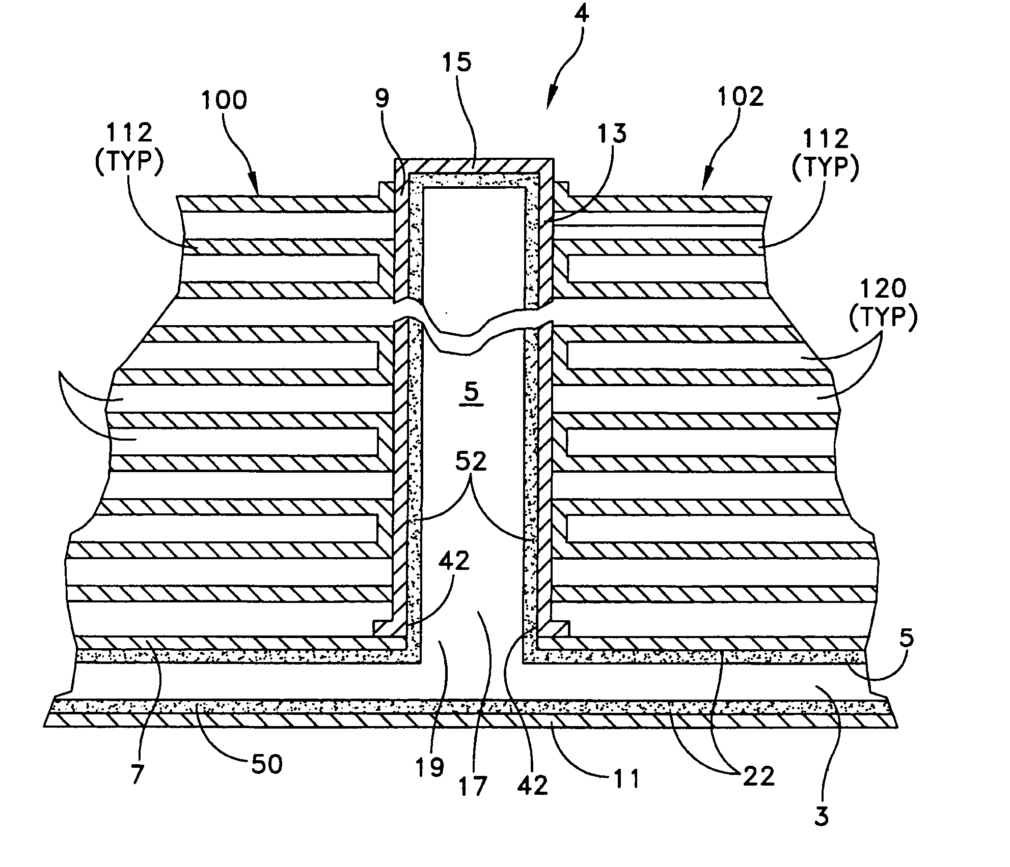
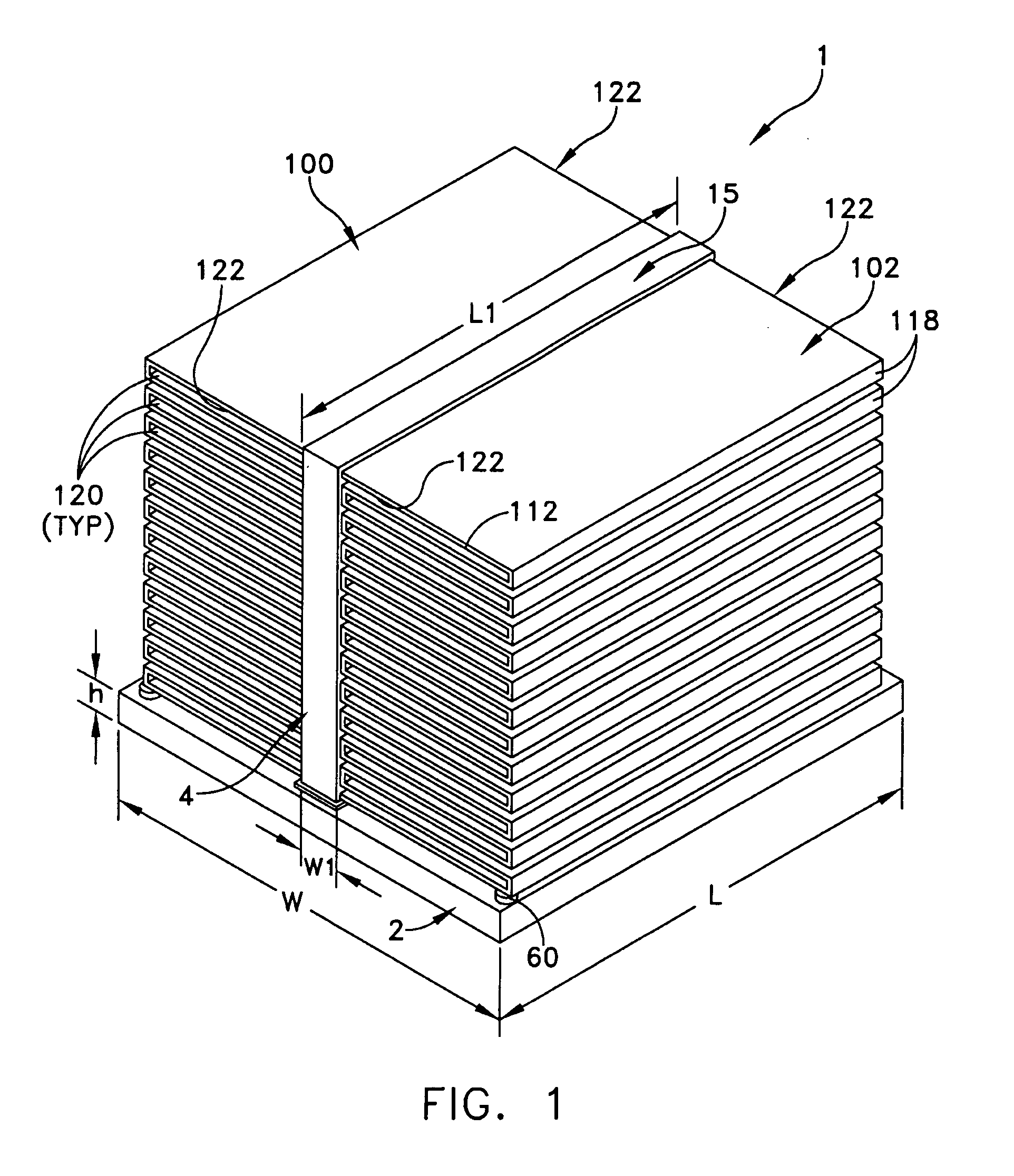
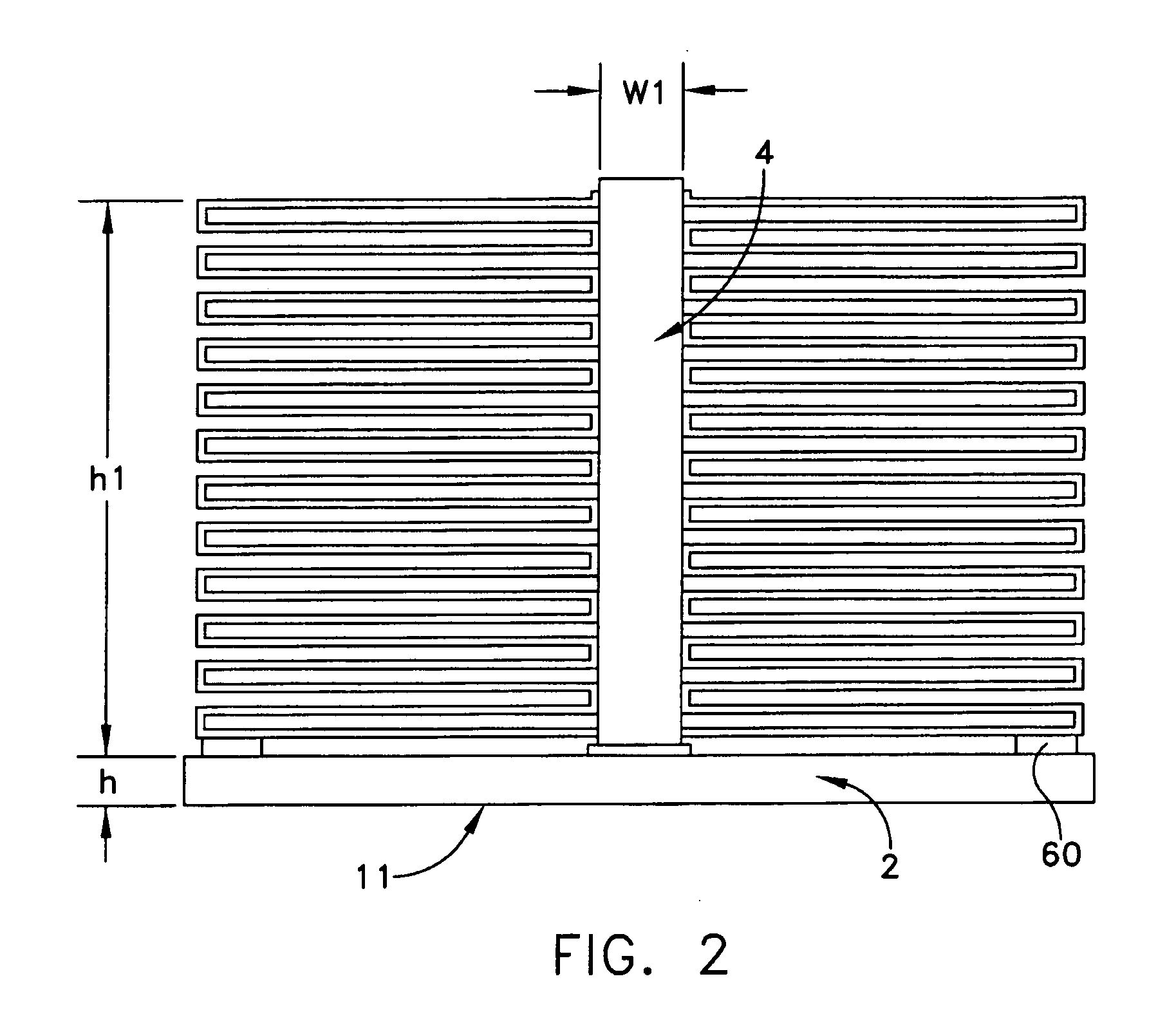
The patent describes a vapor chamber that has a heat pipe attached to it. The vapor chamber has a larger size than the heat pipe and the two parts are connected at their edges. The heat pipe is attached to the vapor chamber in a way that it is narrower and longer than the vapor chamber. The vapor chamber has a wick structure inside it that allows fluid to flow through it. The technical effect of this design is that it allows for better heat transfer and more efficient cooling of the vapor chamber.

Problems solved by technology

The patent text discusses the increasing heat generation in electronic devices and the challenge of managing this heat in a cost-effective and efficient way. The text highlights the need to find effective thermal solutions to reduce system costs and time-to-market, while also addressing the non-uniform heat distribution and the trend towards miniaturization of electronic devices. The technical problem addressed in the patent is to provide a thermal management architecture that can accumulate and transfer variable amounts of thermal energy while avoiding or minimizing the use of non-passive, tandem cooling or refrigeration systems for cooling.

Method used


Image

  • Three dimensional vapor chamber
  • Three dimensional vapor chamber
  • Three dimensional vapor chamber

Examples


Embodiment Construction

[0019] This description of preferred embodiments is intended to be read in connection with the accompanying drawings, which are to be considered part of the entire written description of this invention. The drawing figures are not necessarily to scale and certain features of the invention may be shown exaggerated in scale or in somewhat schematic form in the interest of clarity and conciseness. In the description, relative terms such as “horizontal,”“vertical,”“up,”“down,”“top” and “bottom” as well as derivatives thereof (e.g., “horizontally,”“downwardly,”“upwardly,” etc.) should be construed to refer to the orientation as then described or as shown in the drawing figure under discussion. These relative terms are for convenience of description and normally are not intended to require a particular orientation. Terms including “inwardly” versus “outwardly,”“longitudinal” versus “lateral” and the like are to be interpreted relative to one another or relative to an axis of elongation, o...


PUM


Abstract

A three dimensional vapor chamber is disclosed which has a horizontal vapor chamber portion and a vertical flat heat pipe portion. The interiors of the two portions are in fluid communication and can have a wick material saturated with a working fluid such as water. The vertical flat heat pipe portion can also have fins or other heat exchange structure connected to the exterior thereof to increase heat transfer away from the heat pipe portion. In operation, the vapor chamber portion is placed in contact with a heat source, thus causing the working fluid to evaporate and move into the vertical flat heat pipe portion, where it is condensed. The fluid is then transported back to the vapor chamber portion via capillary action through the wick. The interiors of the two portions may be constructed as a vacuum chamber, so that evaporation of the working fluid can occur at lower temperatures than would occur at atmospheric pressure.

Description


Claims


Application Information

Patent Timeline
Owner CONNORS MATTHEW J
Why Eureka
Try Eureka