
Light box having a solar panel cover

a solar panel and light box technology, applied in the field of light box having a solar panel cover, can solve the problems of low efficiency, low cost of solar panels, and few people finding a large, flat solar panel. achieve the effect of preventing water and debris ingress and reducing costs

Active Publication Date: 2005-08-11
FOGERLIE SIVERT G
View PDF5 Cites 64 Cited by
  • Summary
  • Abstract
  • Description
  • Claims
  • Application Information

AI Technical Summary

Benefits of technology

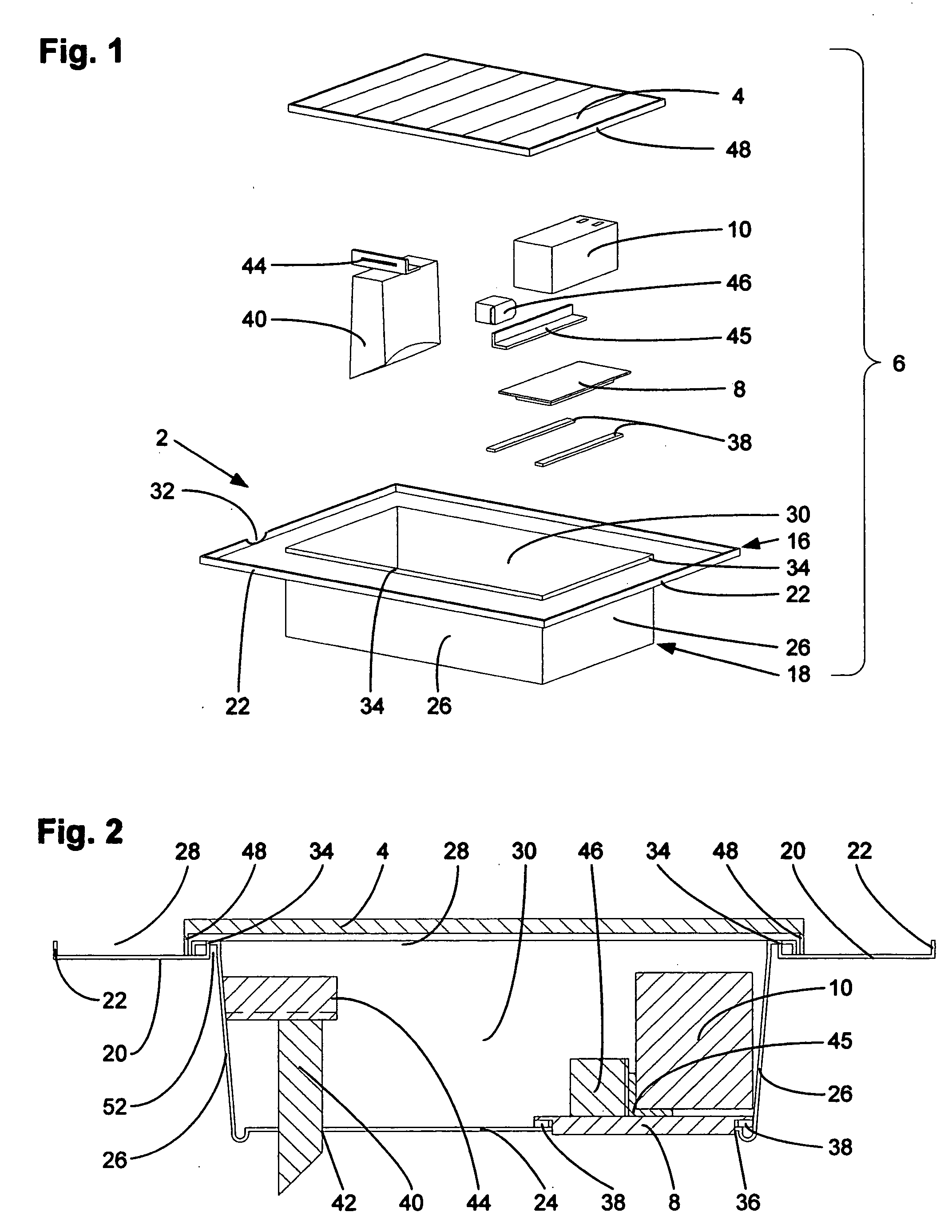
[0004] An additional benefit of the present invention is that the solar panel itself may be used as a protective cover, or lid, for the lower step of the solar light box which contains the weather-sensitive components of the solar powered light assembly. To reduce costs and to more effectively prevent the ingress of water and debris into the lower step of the solar light box, the most preferred embodiment includes a rain barrier ridge where the upper and lower steps of the solar light box meet. The upper and lower steps are also preferably made from a sheet of plastic that is molded, such as by thermoforming, into a single piece part that is durable and aesthetically pleasing.

Problems solved by technology

Unfortunately, larger solar panels used with bright LED lights are frequently targeted by vandals or thieves because the solar panels are easy to spot and are usually located somewhere that is relatively remote, not to mention that the solar panels are expensive.
Additionally, very few people find a large, flat solar panel that is tilted towards the sun to be aesthetically pleasing.
The housing developers failed to run any sort of community power to these CBUs, and it is difficult to persuade the local government to add a street light over one of these public areas, despite the significant safety concerns.
Even though solar powered lighting seems like a clear alternative to address these needs, the prior art has not satisfactorily provided a good choice for those consumers that want an attractive lighting assembly that is not likely to be stolen, and that requires very little maintenance.

Method used


Image

  • Light box having a solar panel cover
  • Light box having a solar panel cover
  • Light box having a solar panel cover

Examples


Embodiment Construction

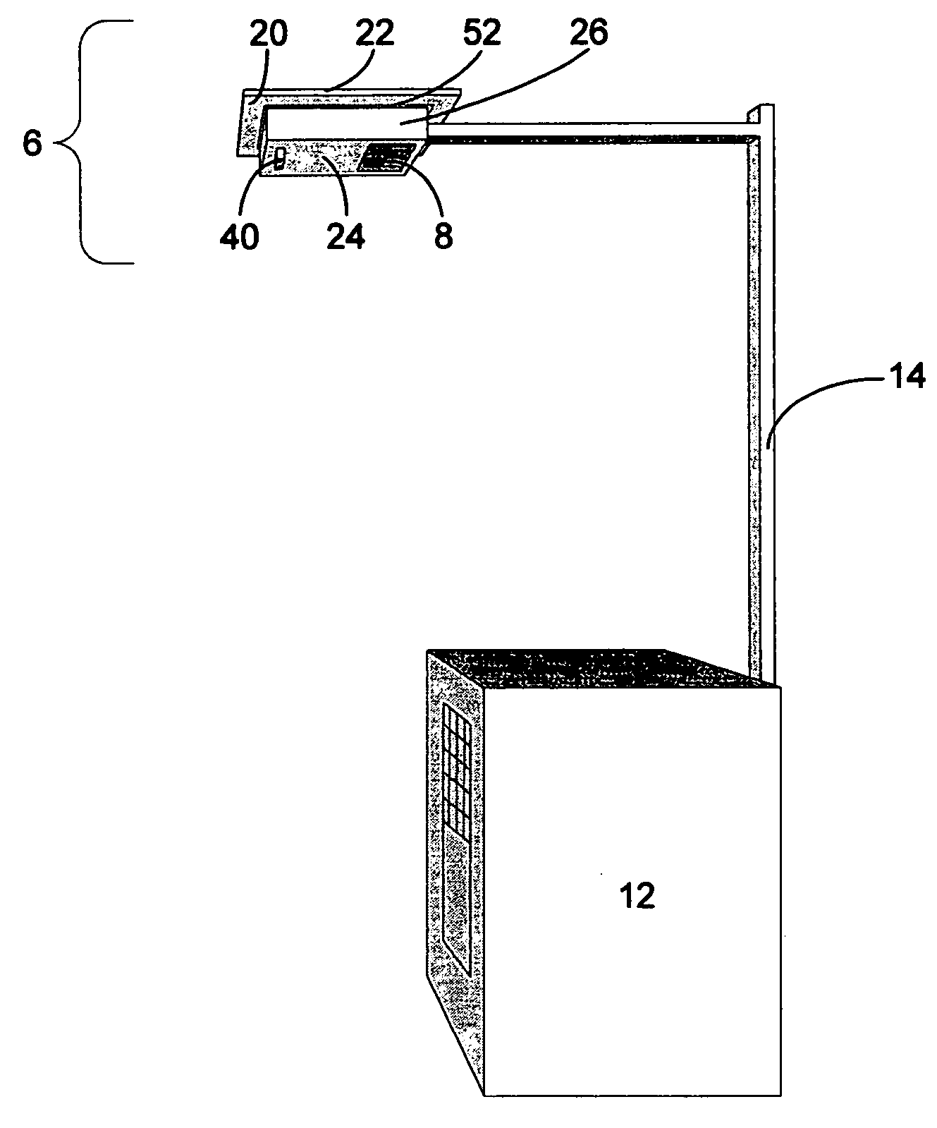
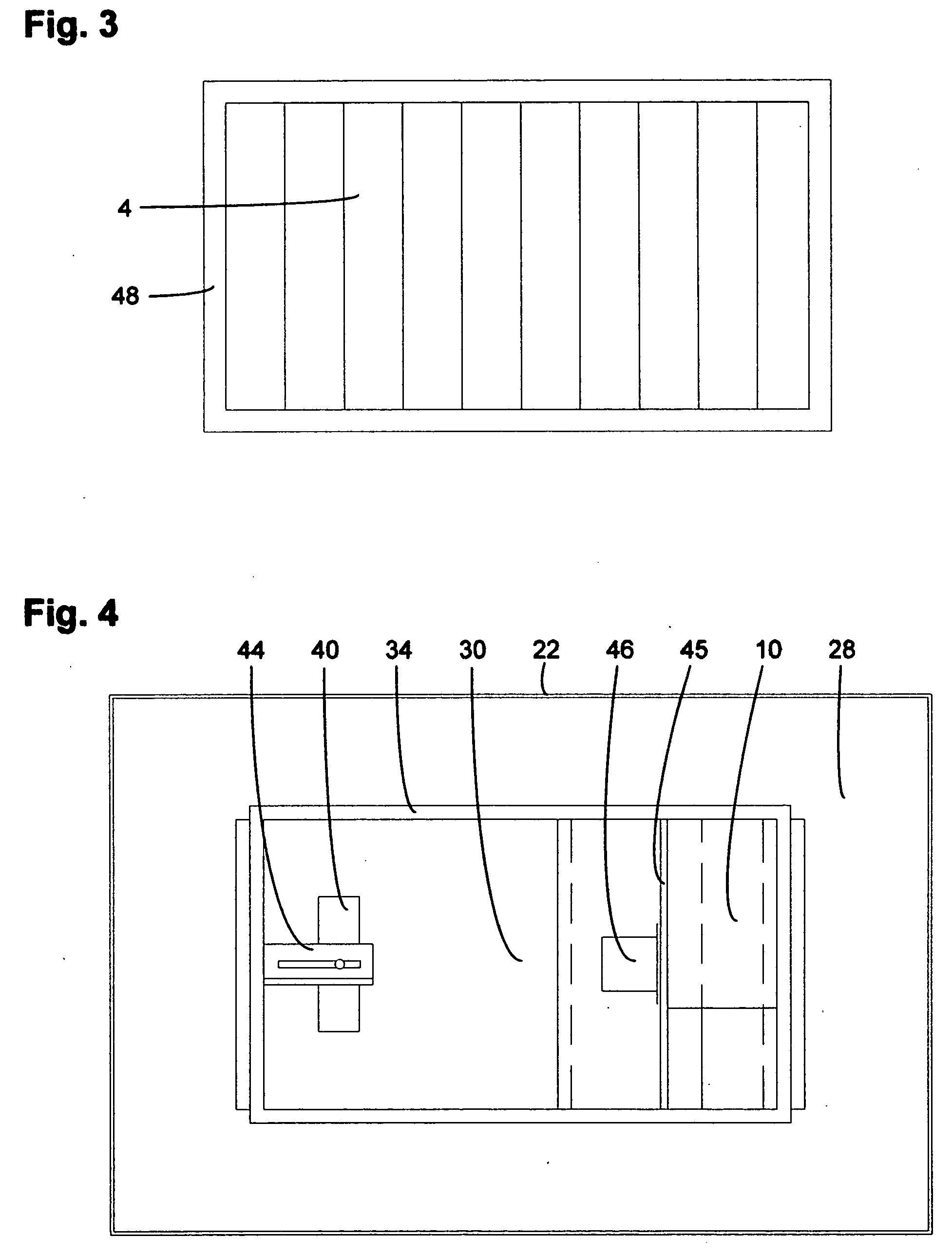
[0039] The focus of the present invention is primarily on the solar light box 2 that conceals the use of a solar panel 4, as seen in FIGS. 1, 2 and 5, but the following description will show how to make an entire solar powered light assembly that is considered to be the best balance of cost and usefulness. The major parts of the solar powered light assembly 6 are the solar light box 2, light source 8, rechargeable battery 10, solar panel 4, and a support structure. These major parts, which will be described in the order just mentioned, are combined to bring the solar powered light assembly together into a low maintenance outdoor lighting solution. Wiring is not shown. The most preferred use of the solar powered light assembly of the present invention is over a cluster box unit (CBU) 12, as shown in FIG. 5, with the light pole 14 being directly attached to the back of the CBU. Additional or alternate features that make the solar powered light assembly more versatile or easier to inst...


PUM


Abstract

The present solar light assembly uses a unique solar light box that has an upper step which visually frames a lower step. The lower step has a deep cavity that houses most of the components of the solar light assembly, such as an LED light source and a 12 volt battery. The lower step is completely covered by a solar panel which functions as a lid in addition to gathering energy that is stored in the battery. The upper step conceals the solar panel from view by a passerby. There is a rain barrier ridge substantially around an opening to the lower step's deep cavity to prevent water that may collect in the upper step from entering the deep cavity. The solar light box is large enough to house additional components, such as a motion sensor or a camera. In the preferred use of the solar light assembly, the solar light box is mounted to a pole that extends over the top of a cluster box unit.

Description

BACKGROUND OF THE INVENTION [0001] Solar panels are frequently used to recharge batteries that power lights at night. Solar powered lights can be observed on walkways (U.S. Pat. No. 5,055,984), mail boxes (U.S. Pat. No. 6,629,766), light poles (U.S. Pat. Nos. 6,060,658, 5,149,188, 4,281,369 and 4,200,904), construction lights (U.S. Pat. No. 4,884,017), or even mounted under the eaves of a building as a security light (U.S. Pat. No. 5,217,296). Interest in solar powered lighting has been fueled by recent advances in white LED technology because the power consumption is lower for the same light output, but the use of LED's has increased the expected light output more than it has decreased the size of the solar panels. Unfortunately, larger solar panels used with bright LED lights are frequently targeted by vandals or thieves because the solar panels are easy to spot and are usually located somewhere that is relatively remote, not to mention that the solar panels are expensive. Additio...

Claims


Application Information

Patent Timeline
IPC IPC(8): F21L4/00F21L13/00F21S8/08F21S9/03F21V15/01F21V23/04F21V33/00
CPCF21S8/086F21S9/037F21V15/01F21V15/005F21V33/0052F21W2131/10F21Y2101/02F21V23/0442F21Y2115/10Y02B20/72
Inventor FOGERLIE, SIVERT G.
Owner FOGERLIE SIVERT G
Learn More