Magnetic fastener

Active Publication Date: 2005-08-18
SJOQUIST CLARISSE
View PDF25 Cites 42 Cited by
  • Summary
  • Abstract
  • Description
  • Claims
  • Application Information

AI Technical Summary

Benefits of technology

[0008] The magnetic fastener is characterized by a handle attached to the exterior of the first flap and interconnected to the first portion of the magnetic assembly for allowing a person to grasp on to the handle to easily operate the magnetic assembly.
[0009] Accordingly, the magnetic fastener is easy to operate and especially useful for persons who lack fine motor coordination. Furthermore, when the magnetic fastener is used on an article of clothing and the handle is embodied as a button, the article of clothing has a standard looking appearance.

Problems solved by technology

Although the Ellis patent appears to provide an effective magnetic fastener, a person with only gross motor skills would have difficulty in operating the fastener.
Persons who lack fine motor skills often have difficulty with daily tasks that most people take for granted.
Putting on and removing clothing is often extremely difficult for those with only gross motor coordination.

Method used


Image

  • Magnetic fastener
  • Magnetic fastener
  • Magnetic fastener

Examples


first embodiment

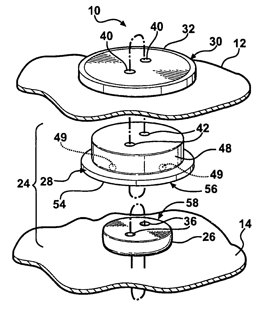
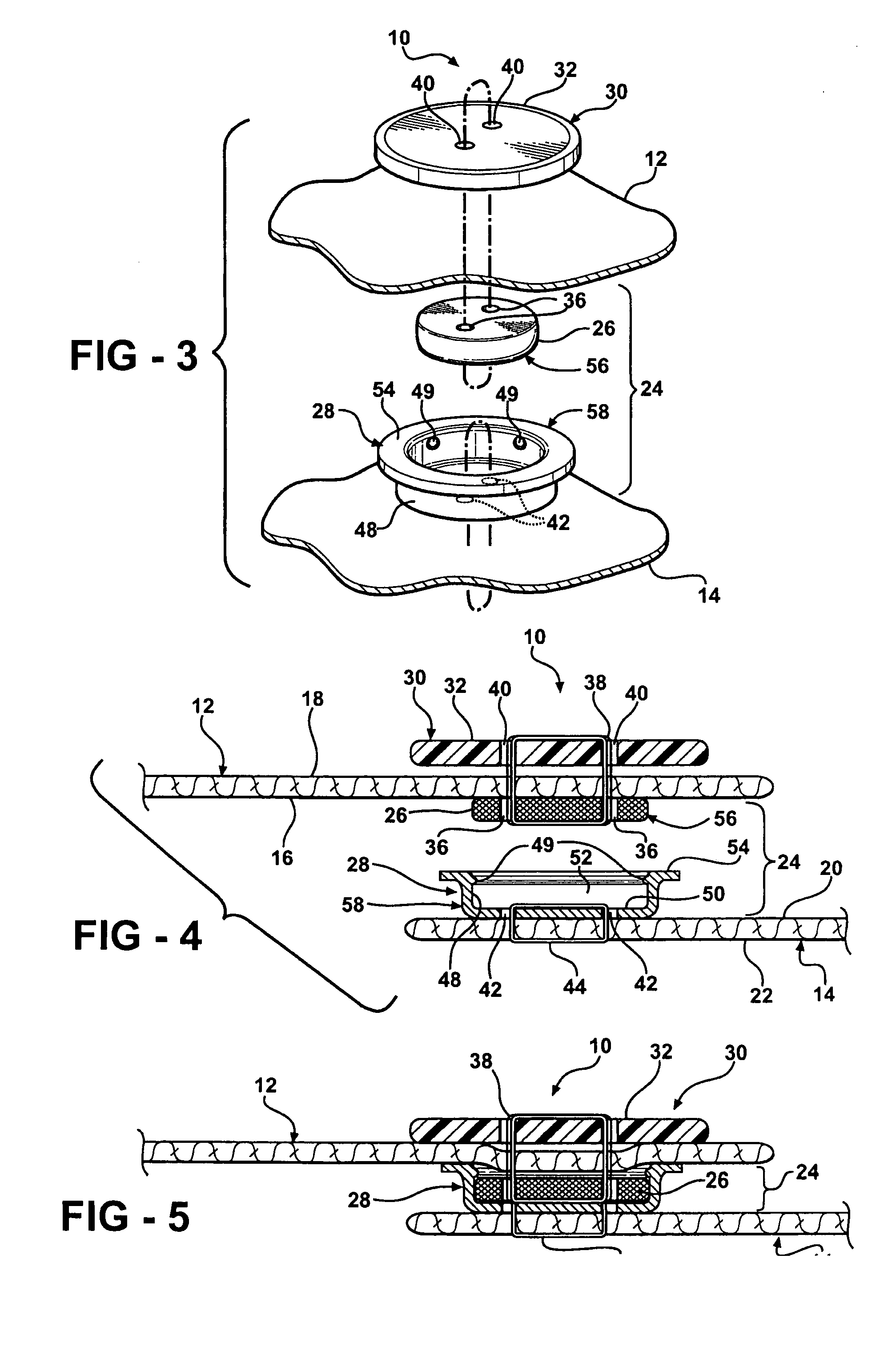
[0020]FIGS. 3, 4, and 5 illustrate, in greater detail, the magnetic fastener 10 to interconnect a first flap 12 of material to a second flap 14 of material. As shown in FIG. 3, the magnetic fastener 10 includes a magnetic assembly 24 which comprises a first portion 56 attached to the first flap 12 and a second portion 58 attached to the second flap 14. The magnetic fastener 10 also includes the handle 30.

[0021] Referring now to FIG. 4, the first flap 12 of material has an inside 16 and an exterior 18. The second flap 14 of material has an outside 20 and an interior 22. The handle 30 is / attached to the exterior 18 of the first flap 12. The magnetic assembly 24 interconnects the first flap 12 to the second flap 14. In this first embodiment, the first portion 56 of the magnetic assembly 24 is further defined as a magnet 26 which forms a magnetic field, while the second portion 58 is further defined as a magnetic element 28. The magnetic element 28 is formed of a magnetically attractive...

second embodiment

[0028] In a second embodiment, as shown in FIGS. 6 and 7, the second portion 58 of the magnetic assembly 24 is the magnet 26 which is attached to the outside 20 of the second flap 14. The first portion 56 is the magnetic element 28 which is attached to the inside 16 of the first flap 12. Again, the button 32 includes button apertures 40 to receive the first thread 38 for attaching the button 32 to the exterior 18 of the first flap 12. It is preferred that the button apertures 40 align with the magnetic element apertures 42 to also accommodate the first thread 38 passing through the magnetic element apertures 42 for attaching the magnetic element 28 to the inside 16 of the first flap 12. The second thread 44 passes through the magnet apertures 36 for attaching the magnet to the outside 20 of the second flap 14.

third embodiment

[0029] In a third embodiment, shown in FIG. 8, the button 32 includes a loop 46. The first thread 38 is received by the loop 46 for attaching the button 32 to the exterior 18 of the first flap 12. The first thread 38 also attaches the magnetic element 28 to the inside 16 of the first flap 12. The second thread 44 passes through the magnet apertures 36 for attaching the magnet to the outside 20 of the second flap 14.


PUM


Abstract

A magnetic fastener (10) for fastening a first flap (12) of material to a second flap (14) of material. A magnet (26) is attached to one of the flaps (12, 14) while a magnetic element (28) is attached to the other flap (14, 12). The natural magnetic attraction between the magnet (26) and the magnetic element (28) keeps the flaps (12, 14) fastened together. A handle (30), preferably embodied as a button (32), is attached to the first flap (12) and interconnected to either the magnet (26) or the magnetic element (28) for allowing the magnetic fastener (10) to be easily opened and closed.

Description

BACKGROUND OF THE INVENTION [0001] 1. Field of the Invention [0002] The subject invention relates to fasteners that function by utilizing magnetism. [0003] 2. Description of the Related Art [0004] Numerous magnetic fasteners that include a magnet and a magnetic element are well known in the prior art. An example of such a magnetic fastener is disclosed in the U.S. Pat. No. 2,397,931 to Robert Ellis. [0005] The Ellis patent discloses a magnet with two magnet apertures. The magnet is sewn onto a first flap using a first thread through the magnet apertures. Likewise, a magnetic element also includes two magnetic element apertures. The magnetic element is sewn onto a second flap opposite the magnet. The magnetic element includes a peripheral wall portion and a planer wall portion to define a cavity. When fastened, the magnet resides in the cavity. The natural magnetic attraction between the magnet and magnetic element keep the magnet and magnetic element fastened together. [0006] Althou...

Claims


Application Information

Patent Timeline
IPC IPC(8): A44B99/00A41F1/00A44B1/28
CPCA41F1/002Y10T24/32Y10T24/3651A44B1/20A44D2203/00
Inventor SJOQUIST, CLARISSE
Owner SJOQUIST CLARISSE
Why Eureka
Try Eureka