High-Pressure Explosive Retention Device

a retention device and high-pressure technology, applied in the direction of ammunition projectiles, weapons, borehole/well accessories, etc., can solve the problems of low reliability of explosive detonation, low reliability of ballistic transfer between multiple explosive elements, and high hydrostatic pressure inside the wellbore, so as to increase the reliability of explosive transfer

Active Publication Date: 2005-08-18
SCHLUMBERGER TECH CORP
View PDF12 Cites 4 Cited by
  • Summary
  • Abstract
  • Description
  • Claims
  • Application Information

AI Technical Summary

Benefits of technology

[0004] In general, methods and apparatus are provided to increase reliability of explosive transfer from one explosive element to another explosive element in the presence of high pressure. For example, an apparatus includes one or more housing sections that provide a sealed space. A first explosive element is in the sealed space. A second explosive element has a first portion in the sealed space, and a second portion outside the sealed space exposed to outside pressure. A gripping mechanism grips a surface of the explosive element to maintain a position of the second explosive element that is exposed to the outside pressure in an axial direction of the second explosive element.

Problems solved by technology

An issue associated with initiating explosives in a wellbore is the presence of a high hydrostatic pressure inside the wellbore, particularly when detonation assemblies to initiate the explosives are exposed to the wellbore pressure.
The presence of high pressure in a wellbore can make explosive detonation less reliable, and the ballistic transfer between multiple explosive elements less reliable.
In the presence of high pressure, explosive elements such as a detonating cord or a booster explosive are compacted, which causes the explosive elements to become desensitized.
As a result, the transfer of explosive energy from the detonator to the other side of the barrier may not reliably detonate the explosive element.

Method used


Image

  • High-Pressure Explosive Retention Device
  • High-Pressure Explosive Retention Device
  • High-Pressure Explosive Retention Device

Examples


Embodiment Construction

[0008] In the following description, numerous details are set forth to provide an understanding of the present invention. However, it will be understood by those skilled in the art that the present invention may be practiced without these details and that numerous variations or modifications from the described embodiments may be possible.

[0009] As used here, the terms “up” and “down”; “upper” and “lower”; “upwardly” and “downwardly”; “upstream” and “downstream”; “above” and “below”; and other like terms indicating relative positions above or below a given point or element are used in this description to more clearly described some embodiments of the invention. However, when applied to equipment and methods for use in wells that are deviated or horizontal, such terms may refer to a left to right, right to left, or other relationship as appropriate.

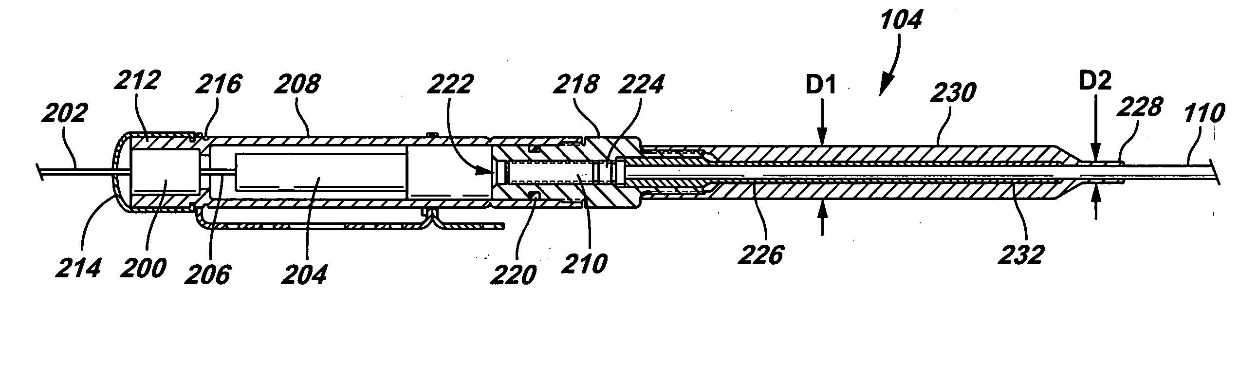
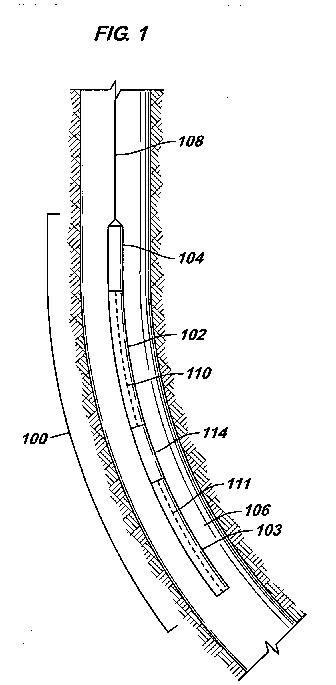
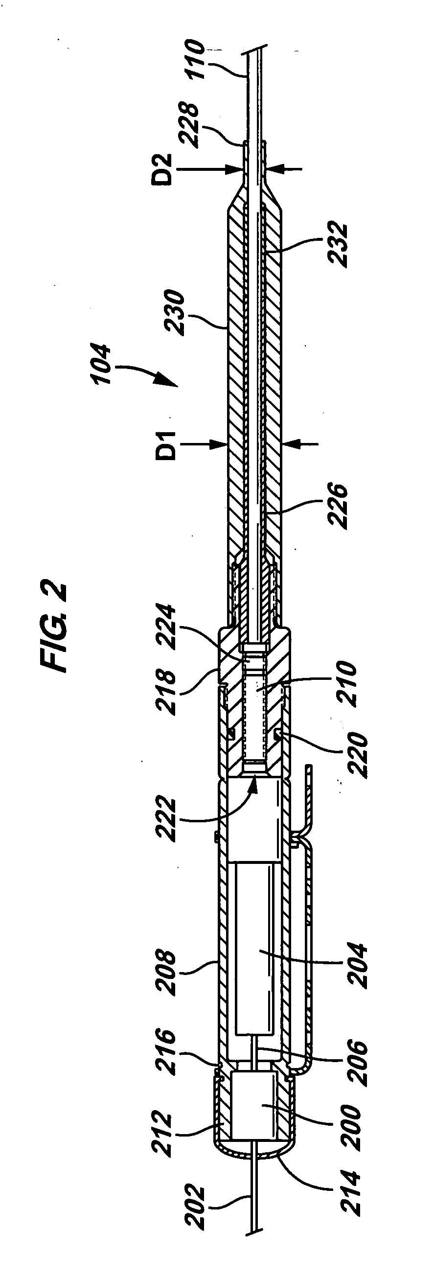
[0010]FIG. 1 illustrates a perforating gun string 100 that includes perforating guns 102 and 103 and a detonator assembly 104 according ...


PUM


Abstract

An apparatus and method for reliably activating explosives includes providing one or more housing sections that define a sealed space. A first explosive element is provided in the sealed space, and a second explosive element has a first portion inside the sealed space, and a second portion outside the sealed space exposed to outside pressure. A gripping mechanism grips a surface of the second explosive element to maintain a position of the second explosive element that is exposed to the outside pressure in an axial direction of the second explosive element.

Description

BACKGROUND OF INVENTION [0001] In completing a well, perforations are often extended into the formation surrounding a wellbore to enable communication of well fluids between the formation and the wellbore. Perforation is accomplished by use of perforating guns that are run into the wellbore from a well surface. Such perforating guns typically include shaped charges that, when initiated, produce perforating jets that cut through a casing or liner and extend perforating tunnels into the surrounding formation. The shaped charges are typically connected to a detonating cord, which is in turn connected to a detonation assembly (or firing head). To activate the perforating gun, an input signal (such as an electrical signal, optical signal, pressure pulse signal, mechanical signal, or another signal) is provided to the detonation assembly, which causes initiation of the detonating cord. A detonation wave traveling down the detonating cord causes detonation of the shaped charges. [0002] Exp...

Claims


Application Information

Patent Timeline
Patent Type & Authority Applications(United States)
IPC IPC(8): E21B43/1185F42D1/04
CPCF42D1/043E21B43/1185
Inventor MARKEL, DANIEL C.PHILLIPS, LARRY W.
Owner SCHLUMBERGER TECH CORP
Why Eureka
Try Eureka