Sealable bag with excess air evacuation blocking structure

a technology of blocking structure and sealing bag, which is applied in the direction of flexible container closure, ventilation means, transportation and packaging, etc., can solve the problems of affecting the quality of any food stored within the bag, and causing the volume of the bag, so as to facilitate the evacuation of excess air

Inactive Publication Date: 2005-08-18
FRENKIL LEONARD
View PDF12 Cites 19 Cited by
  • Summary
  • Abstract
  • Description
  • Claims
  • Application Information

AI Technical Summary

Benefits of technology

[0010] Based on the foregoing, it is an object of the present invention to provide sealable bags that facilitate the evacuation of excess air that would otherwise be trapped within the sealable bag upon closure.

Problems solved by technology

A common problem encountered during the use of many such sealable bags is that excess air becomes trapped within the bag when it is sealed.
Trapped excess air has the potential to adversely affect the quality of any food stored within the bag.
And, trapped excess air causes the bag—filled or otherwise empty—to occupy a greater volume than necessary.
Thus, for instance, a resealable bag with food stuff stored within may not fit in a particular storage area, such as a refrigerator drawer, with the additional volume supplied by the accompanying trapped excess air; whereas, if the trapped excess air was substantially removed, the storage area could accommodate the volume supplied by the food stuff and bag alone.
Each of these suggested remedies suffer, however, from several problems of their own.
All of these suggested remedies are relatively complex and would seem to add significant additional expense to the manufacture of such resealable bags.
Other suggested remedies found in the prior art are even more complex.

Method used


Image

  • Sealable bag with excess air evacuation blocking structure
  • Sealable bag with excess air evacuation blocking structure
  • Sealable bag with excess air evacuation blocking structure

Examples


Embodiment Construction

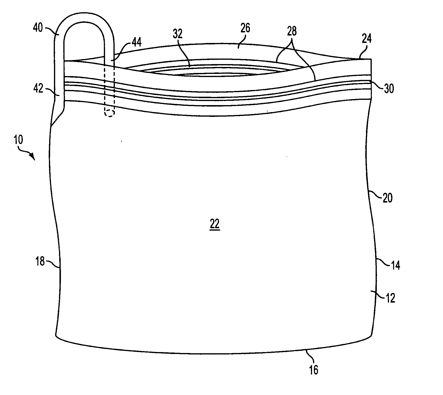
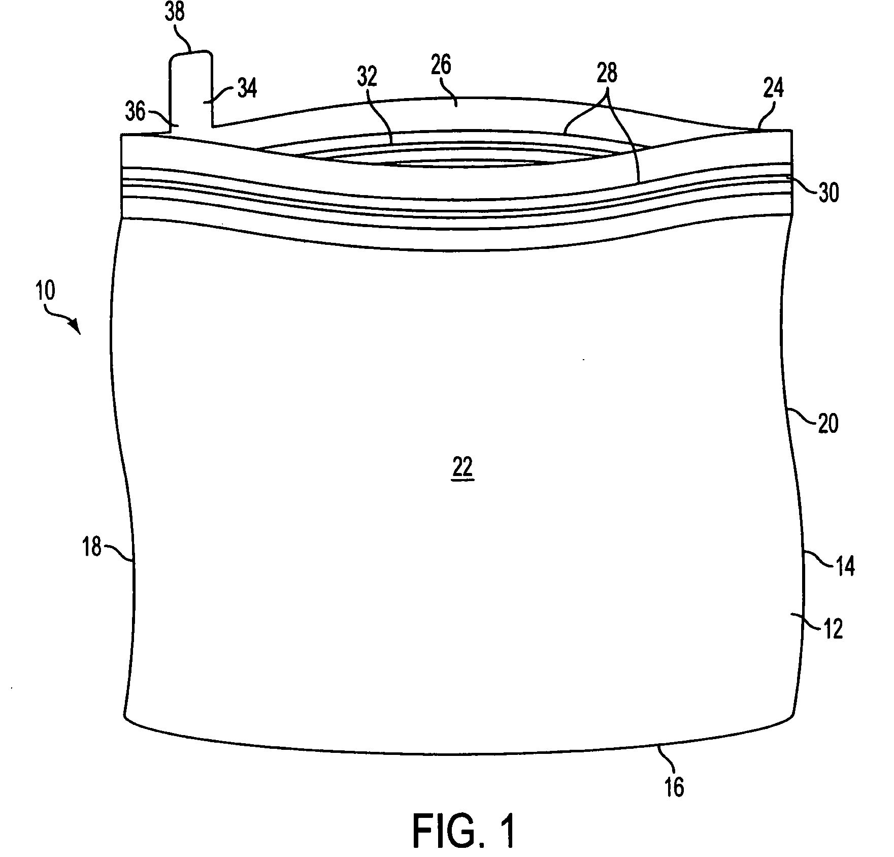
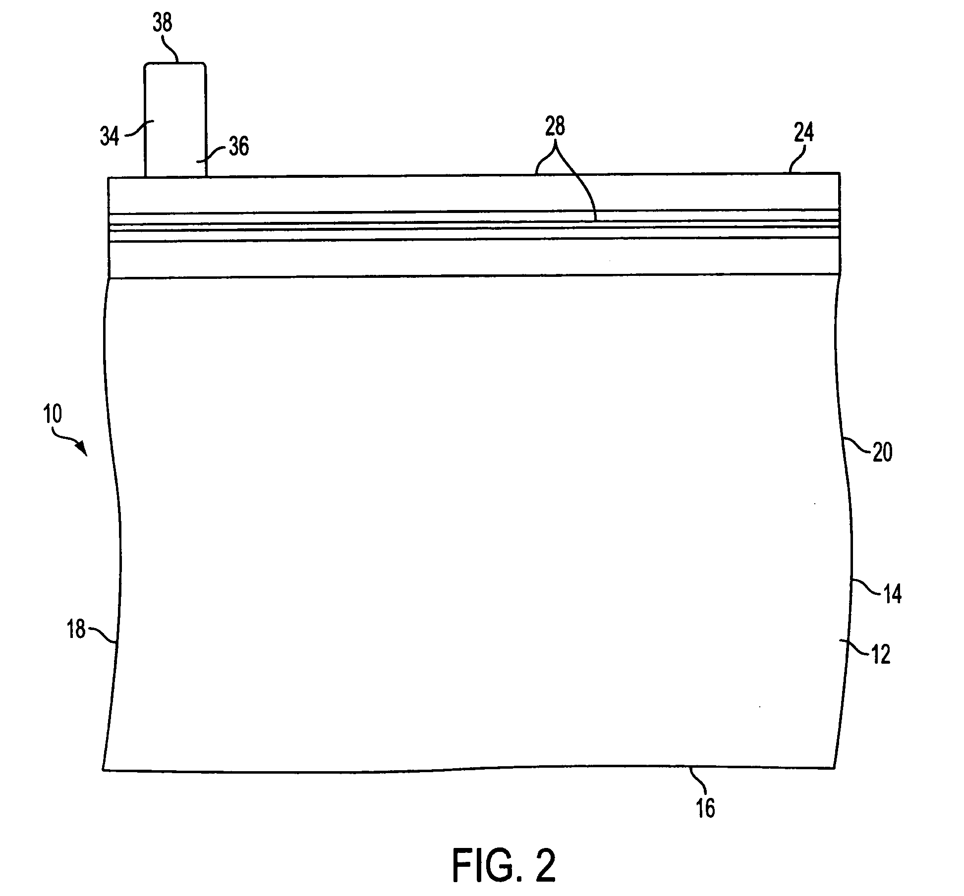
[0032] With reference to the drawings, FIGS. 1-8 depict the preferred and other embodiments of the present invention, resealable bags 10.

[0033] Referring to FIGS. 1 and 2, the preferred embodiment of the present invention, the resealable bag 10 comprises a first panel 12 and a second panel 14, each panel being generally square or rectangular and having four edges. Said first and second panels 12, 14 are substantially permanently sealed, preferably heat-sealed, along three edges forming a bottom end 16, a left side 18, and a right side 20 of the bag 10, and thus forming a pouch 22. The fourth edge of the panels is not permanently sealed and forms a top end 24, defining an opening 26 when unsealed, thus allowing ingress and egress of items in and out of the pouch 22 through the opening 26. The top end 24 has an interlocking tongue and groove system 28 for selective sealing and unsealing the opening 26. The interlocking tongue and groove system 28 includes a tongue strip 30 and a groo...


PUM


Abstract

A sealable bag construction to facilitate the evacuation of excess air that would otherwise be trapped within the sealable bag upon closure. The construction comprises incorporating a blocking structure into the sealable bag by, for instance, attaching, integrally or otherwise, a spacer to material near the opening of a sealable bag, including resealable bags, such that an obstructing portion of the spacer may be temporarily placed in the opening of the bag to prevent the complete sealing thereof, or, in lieu of the spacer, a partial deformation of the sealing means for the sealable bag wherein the deformation is located to provide a temporary stop near, but not at, one end of the opening of the sealable bag. Excess air that would otherwise remain within the bag may thereby be evacuated before the obstructing portion of the spacer is removed (or the deformation is pushed by) and the opening completely sealed.

Description

BACKGROUND OF THE INVENTION [0001] 1. Field of the Invention [0002] The present invention relates to sealable bags. In a specific aspect, it relates to means for more easily evacuating undesirable excess air from a resealable bag. [0003] 2. Description of Related Art [0004] Sealable bags are well-known in the art. For instance, Zip-Lock® and Glad-Lock® resealable bags are commonly used for storage of food and other household items. Such resealable bags generally have an opening running substantially the length of one end of the bag and have opposing interlocking strips that run the length of the opening for sealing the bag. When sealed, theses bags are substantially airtight, although air may ingress or egress over the passage of time. Other types of sealable bags exist as well, such as those disclosed in U.S. Pat. No. 6,530,471, issued to Tsuyuguchi, U.S. Pat. No. 6,484,879, issued to Desmarais, U.S. Pat. No. 6,231,553, issued to Hulett, and U.S. Pat. No. 6,029,810, issued to Chen....

Claims


Application Information

Patent Timeline
Patent Type & Authority Applications(United States)
IPC IPC(8): B65D33/01B65D33/25B65D81/20
CPCB65D33/01B65D2205/00B65D33/2508
Inventor FRENKIL, LEONARD
Owner FRENKIL LEONARD
Why Eureka
Try Eureka