Cutting insert with coolant delivery and method of making the cutting insert

a cutting insert and coolant delivery technology, applied in the field of cutting inserts, can solve the problems of reducing or shortening increasing overall operating costs, and reducing overall production efficiency, and reducing the useful tool life of cutting inserts

Active Publication Date: 2010-07-08
KENNAMETAL INC
View PDF30 Cites 22 Cited by
  • Summary
  • Abstract
  • Description
  • Claims
  • Application Information

AI Technical Summary

Problems solved by technology

It is well-known that excessive heat at the insert-chip interface can negatively impact upon (i.e., reduce or shorten) the useful tool life of the cutting insert.
As can be appreciated, a shorter useful tool life increases overall operating costs and decreases overall production efficiency.
A decrease in plastic deformation resistance increases the risk for breakage of the cutting insert.
U.S. Pat. No. 5,775,854 to Wertheim points out that a rise in the working temperature leads to a decrease in hardness of the cutting insert with a consequent increase in wear of the cutting insert.
It is readily apparent that in a chipforming and material removal operation, higher operating temperatures at the insert-chip interface can have a detrimental impact on the useful tool life.
These higher temperatures can cause premature breakage and / or excessive wear, which results in reduction or shortening of the useful tool life.
The build up of chip material on the cutting insert in this fashion is an undesirable occurrence that can negatively impact upon the performance of the cutting insert, and hence, the overall material removal operation.
It is undesirable for the cutting insert to re-cut a chip already removed from the workpiece.
However, the advantages extant with such a cutting insert that has a coolant delivery feature can diminish when the cutting insert has only one cutting edge.
While these powder metallurgical techniques are satisfactory, the use thereof to make cutting tools of a more complex geometry may raise a manufacturing challenge.

Method used


Image

  • Cutting insert with coolant delivery and method of making the cutting insert
  • Cutting insert with coolant delivery and method of making the cutting insert
  • Cutting insert with coolant delivery and method of making the cutting insert

Examples


Embodiment Construction

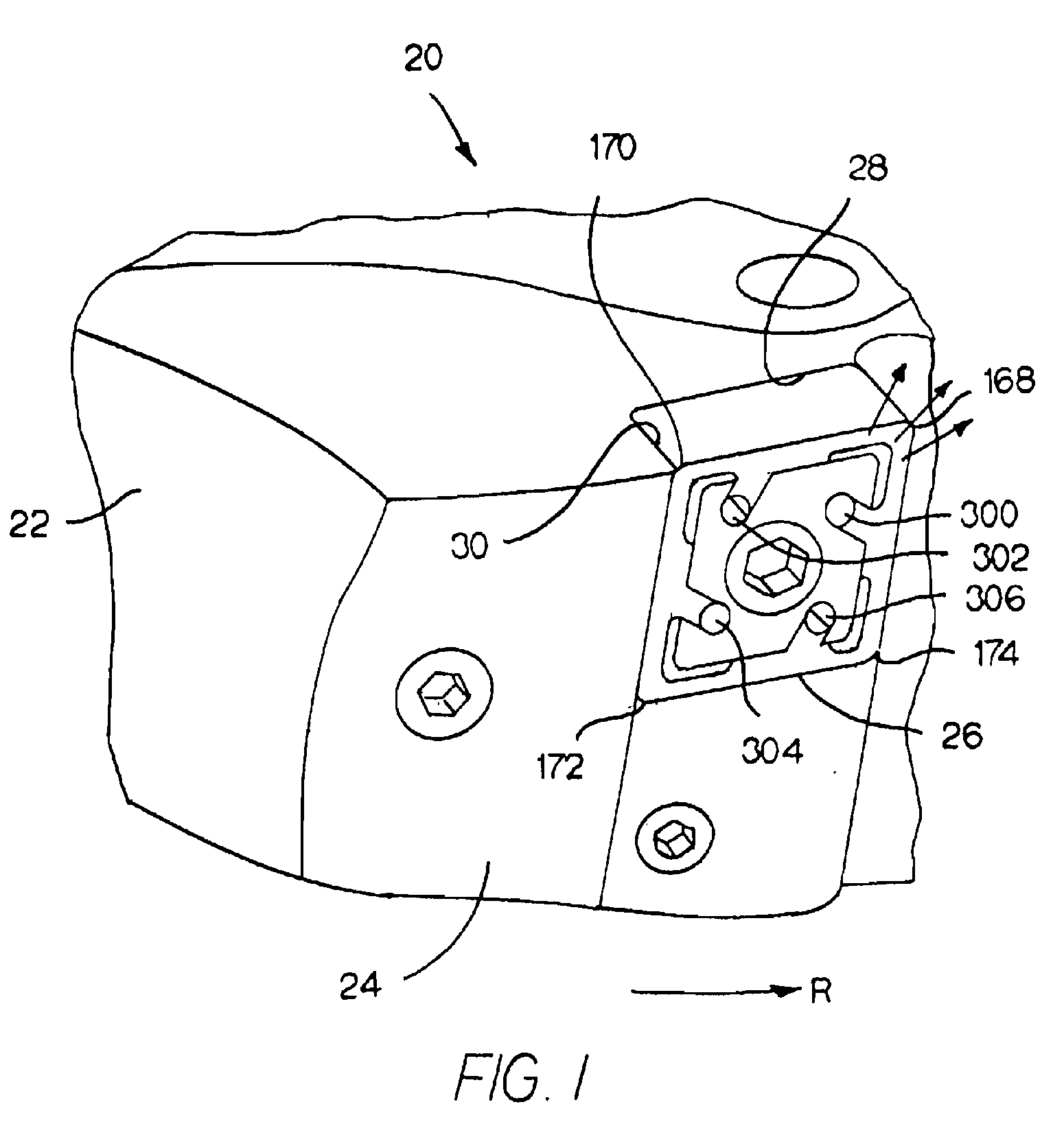
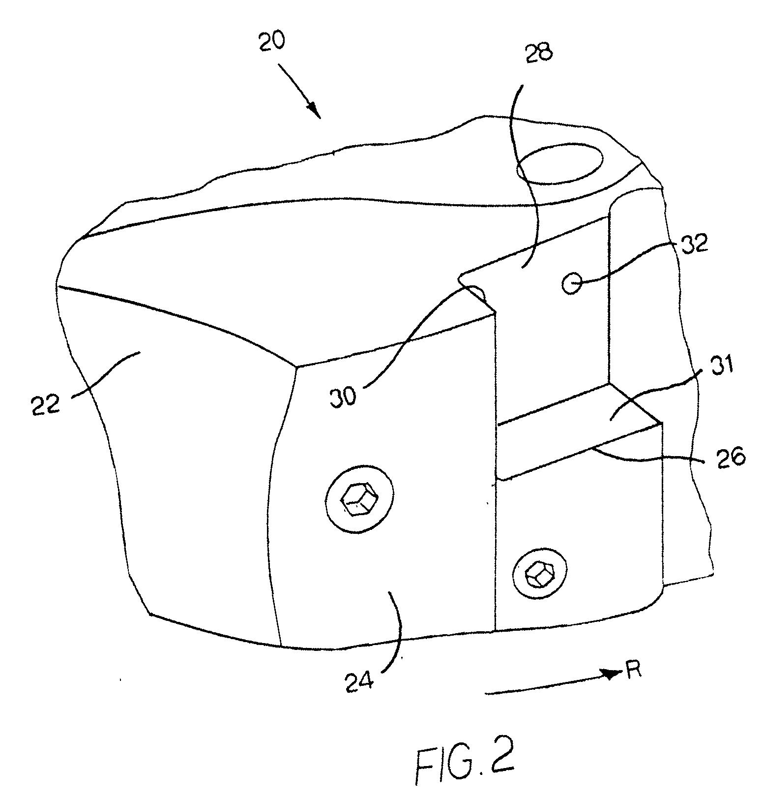
[0028]Referring to the drawings, FIGS. 1 and 2 illustrate a portion of a milling cutter assembly of the invention generally designated as 20 wherein the milling cutter assembly 20 is for use in chipforming and material removal operations. In this specific embodiment, the cutter assembly is useful in a milling operation. Pending U.S. patent application Ser. No. 11 / 654,833 (filed Jan. 18, 2007) to Prichard et al. for a Milling Cutter and Milling Insert with Coolant Delivery, assigned to Kennametal Inc. of Latrobe, Pa., USA, shows and describes an exemplary milling cutter. In such an operation, the milling cutter removes material from a workpiece.

[0029]A material removal operation that removes material from the workpiece in the form of chips typically is known by those skilled in the art as a chipforming material removal operation. The book Machine Shop Practice [Industrial Press Inc., New York, N.Y. (1981)] by Moltrecht presents at pages 199-204 a description, inter alia, of chip form...


PUM


Abstract

An assembly of components for forming upon consolidation of the components a cutting insert for use in chipforming and material removal from a workpiece wherein the cutting insert receives coolant from a coolant source. The assembly comprises a cavity member that presents opposite first and second rake surfaces and a flank surface. The cavity member further presents a first cutting edge at the juncture of the first rake surface and the flank surface. The cavity member further has a first depression in the first rake surface that is generally adjacent to the first cutting edge. The cavity member has a first cavity channel in communication with the first depression. The assembly also has a first core member that has a first core channel and a first flange wherein when the components are assembled, the first core channel is adjacent to the first cavity channel and the first flange is adjacent to the first depression. The assembly also has a second core member which has a second flange containing a fifth notch and the second core member further containing a fifth notch channel opening into the fifth notch. When the components are assembled, the fifth notch is adjacent to the second rake surface and the fifth notch channel is adjacent to the first cavity channel. Upon consolidation of the components, the cavity member, the first core member and the second core member join together so that the first depression and the first flange define a first fluid spray chamber, and the first cavity channel and the first core channel and the fifth notch channel join together to form a fifth internal fluid passageway, which provides fluid communication from the fifth notch adjacent to the second rake surface to the first fluid spray chamber adjacent to the first rake surface.

Description

BACKGROUND OF THE INVENTION[0001]The invention relates to a cutting insert used for chipforming and material removal operations, as well as a method for making the cutting insert. More specifically, the invention pertains to a cutting insert used for chipforming and material removal operations, as well as a method for making the cutting insert, wherein there is enhanced delivery of coolant adjacent the interface between the cutting insert and the workpiece (i.e., the insert-chip interface) to diminish excessive heat at the insert-chip interface.[0002]In a chipforming and material removal operation (e.g., a milling operation), heat is generated at the insert-chip interface. It is well-known that excessive heat at the insert-chip interface can negatively impact upon (i.e., reduce or shorten) the useful tool life of the cutting insert. As can be appreciated, a shorter useful tool life increases overall operating costs and decreases overall production efficiency. Hence, there are readil...

Claims


Application Information

Patent Timeline
Patent Type & Authority Applications(United States)
IPC IPC(8): B26D3/00
CPCB22F2998/00B23B27/10B23B27/145B23B2200/086B23B2250/12B23C5/207Y10T407/23B23C5/28Y10T407/235Y10T407/14Y10T407/245B22F3/225B23C5/202B23C5/282
Inventor NELSON, JOSEPH V.
Owner KENNAMETAL INC
Why Eureka
Try Eureka