
Shaper router and method

a router and router technology, applied in the field of routing, can solve the problems of poor surface finish and chattering, typical carbide or high-speed steel tools do not produce a desirable surface finish, and the cutters and carbide and steels are easy to dull, so as to reduce the production time, improve the surface finish, and reduce the delamination

Active Publication Date: 2006-08-15
THE BOEING CO
View PDF12 Cites 22 Cited by
  • Summary
  • Abstract
  • Description
  • Claims
  • Application Information

AI Technical Summary

Benefits of technology

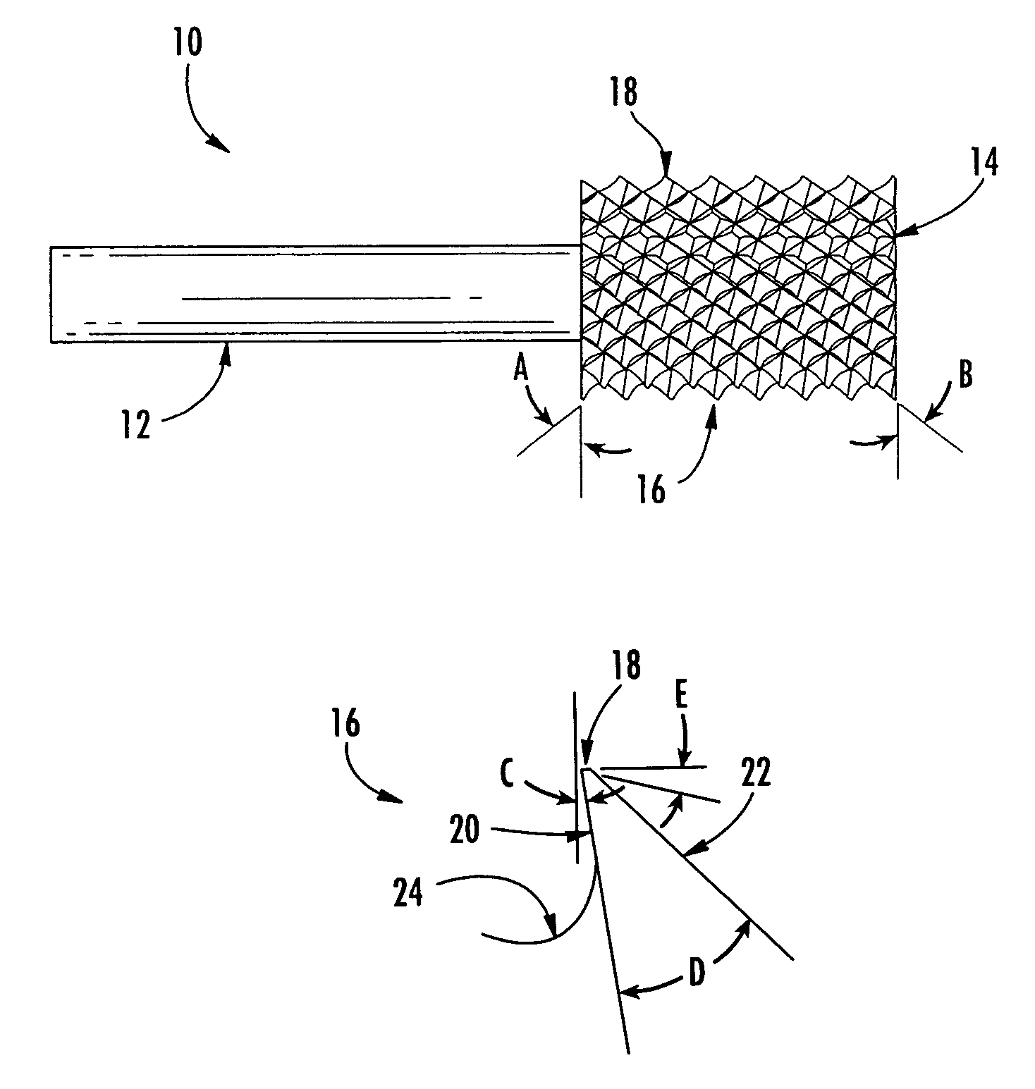
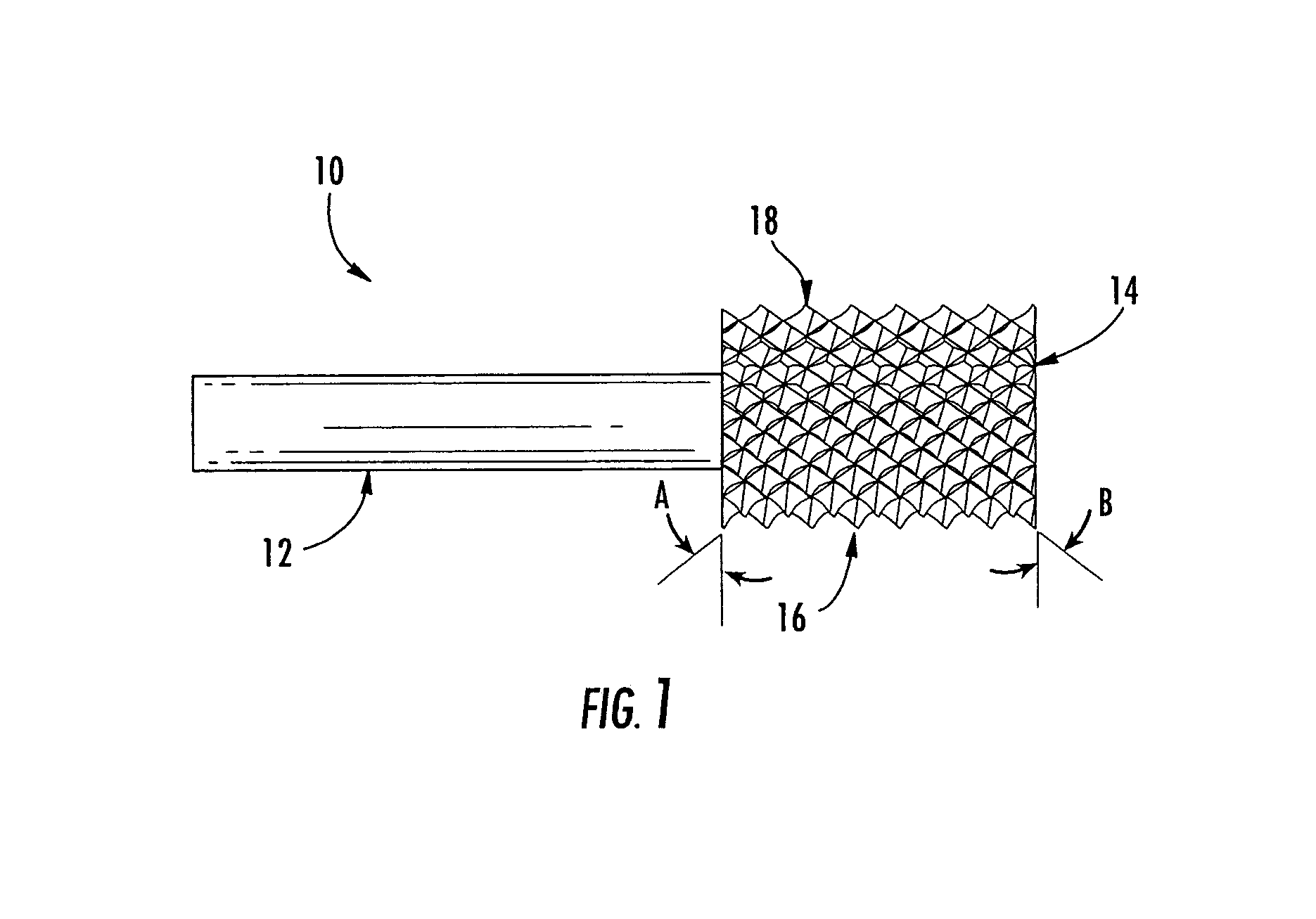
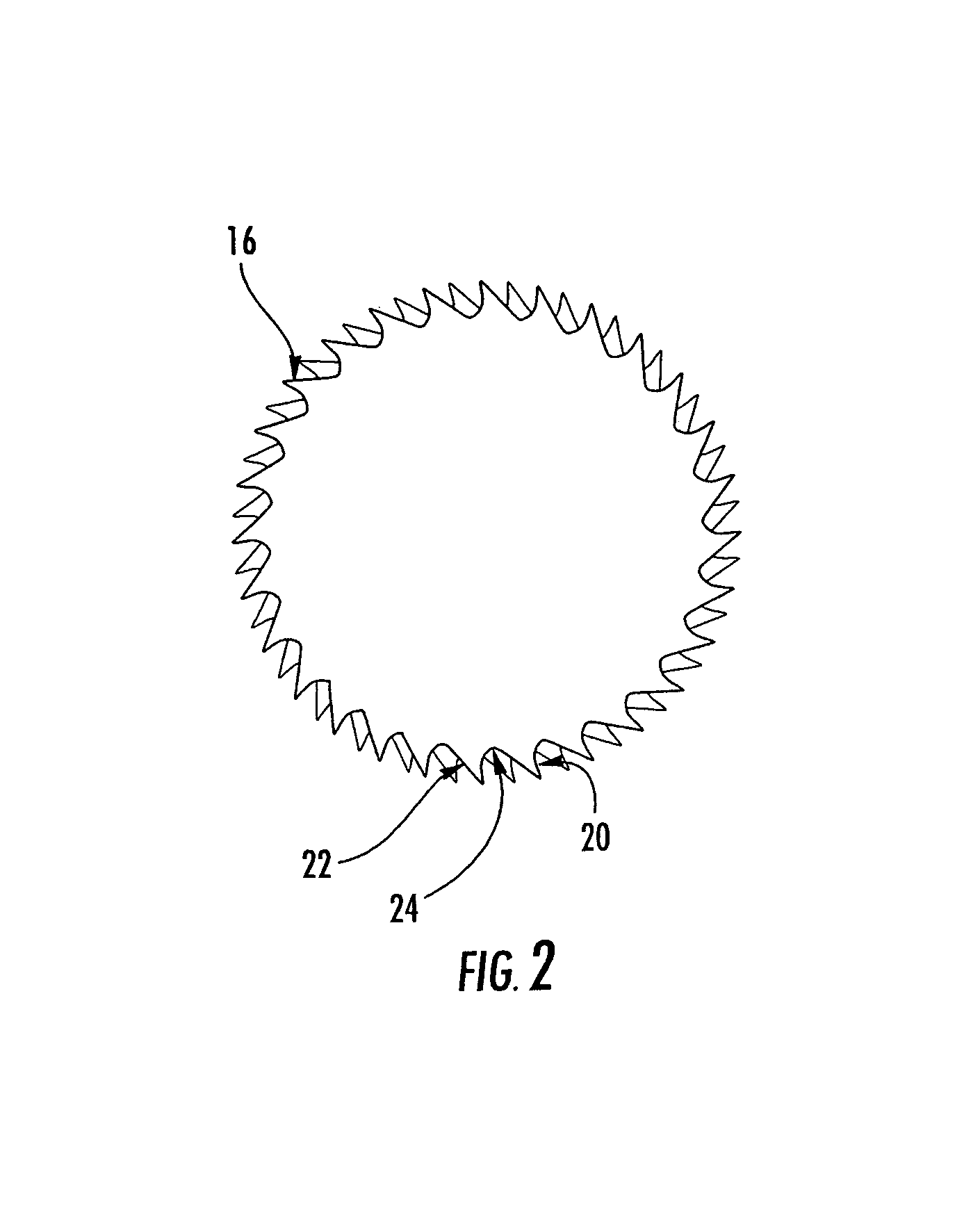
The present invention provides an improved routing tool for cutting various materials that includes a cylindrical shaft member with cutting teeth. The cutting teeth have a unique design that includes a first cutting edge and a second cutting edge, as well as non-cutting edges that allow for smooth transition between the cutting edges. The cutting teeth also have a flat that extends resulting in a circular land on an outside diameter of the cutting portion. The tool includes a motor for rotating the cutting portion. The cutting tooth geometry reduces delamination and improves surface finish when cutting composite material. The cutting tooth alignment also allows for improved chip evacuation and reduces heat generated during the cutting process. The invention can thus produce a machined surface finish of about 125 root-mean-square average (RMS) or better, and does not produce any delamination.

Problems solved by technology

Typical carbide or high-speed steels tools do not produce a desirable surface finish due to the heat generated and the abrasive nature of the graphite.
Thus, the router must be able to cut and evacuate chips rapidly in order to avoid excessive heat production, which ultimately leads to poor surface finish and chattering.
Carbide and steel cutters dull easily, which produces excessive heat.
Delamination refers to separation of the layers of composite material and leads to a poor edge finish, which ultimately needs hand sanding to eliminate the delamination.
Similarly, diamond coated tools do not produce an acceptable surface finish on the part, and hand sanding is usually required to clean up the parts.
Also, diamond pointed tools usually have sharp points that wear out quickly and chip off easily.

Method used


Image

  • Shaper router and method
  • Shaper router and method
  • Shaper router and method

Examples


Embodiment Construction

[0025]The present invention now will be described more fully hereinafter with reference to the accompanying drawings, in which some, but not all embodiments of the invention are shown. Indeed, this invention may be embodied in many different forms and should not be construed as limited to the embodiments set forth herein; rather, these embodiments are provided so that this disclosure will be thorough and complete, and will fully convey the scope of the invention to those skilled in the art. Like numbers refer to like elements throughout.

[0026]Referring now to the drawings and, in particular, to FIG. 1, there is shown a router 10 according to one embodiment of the present invention. The term “router” is not meant to be limiting, and it is understood that the router 10 could by any rotary tool for cutting, trimming, shaping, or forming a variety of patterns, grooves, shapes or holes in a workpiece such as a laminated composite material. Thus, terms such as cutter, milling cutter, or t...


PUM


Abstract

A routing tool for cutting material and an associated apparatus and method are provided. The tool includes a substantially cylindrical shaft member having a shank portion and a cutting portion. The cutting portion includes a plurality of cutting teeth disposed peripherally about a first helix and an intersecting second helix. Each cutting tooth defines a first cutting clearance on a first cutting edge and a first clearance on a first non-cutting edge. The cutting tooth defines a second cutting clearance on a second cutting edge and a second clearance on a second non-cutting edge. A flat extends on each cutting tooth resulting in a circular land on an outside diameter of the cutting portion.

Description

BACKGROUND OF THE INVENTION[0001]1) Field of the Invention[0002]The present invention relates to routing and, more specifically, to a tool and method for cutting and shaping materials using a router.[0003]2) Description of Related Art[0004]Routing is a process used to trim or cut various metal, plastic, and ceramic materials. Routers can also be used to cut composite laminated materials such as graphite. Composite laminated materials are commonly used in the airline and automotive industries due to its high strength to weight ratio, as well as its versatility to accommodate a variety of technical needs. Stiffer materials such as graphite or boron are typically embedded as fibers within a metallic or nonmetallic sheet. Alternatively, sheets of stiffer materials can be laminated to metallic or nonmetallic sheets. An example of a typical composite material is fiberglass. Because of the composite material's high strength, the router must be designed to withstand high resistance and fric...

Claims


Application Information

Patent Timeline
Patent Type & Authority Patents(United States)
IPC IPC(8): B23C5/10
CPCB23C5/10B23C2210/326Y10T407/1946Y10T407/195Y10T407/1958Y10T407/1815Y10T407/181
Inventor AHRNKIEL, ROGER E.PENSE, BRADLEY A.
Owner THE BOEING CO
Learn More