Touch sensitive display for a portable device

a touch sensitive display and portable device technology, applied in the direction of mechanical pattern conversion, identification means, instruments, etc., can solve the problems of inability to detect a plurality of touches on conventional touch sensitive displays, high effort put into providing intuitive interaction mechanisms, and significant progress in user interface, etc., to reduce manufacturing complexity and cost, improve mechanical performance, and simple and convenient implementation

Inactive Publication Date: 2012-12-04
SAMSUNG ELECTRONICS CO LTD
View PDF6 Cites 100 Cited by
  • Summary
  • Abstract
  • Description
  • Claims
  • Application Information

AI Technical Summary

Benefits of technology

[0013]The invention allows for a pressure sensitive layer to be used which preferably requires little or no deformation in order to modify conductivity. Therefore, the mechanical stress and sensitivity of the active matrix display element and the conductor layers may be reduced significantly leading to improved reliability.
[0033]This allows for a particularly advantageous implementation allowing for reduced complexity and component cost of the touch sensitive display thus reducing manufacturing cost.

Problems solved by technology

In addition, the user interface has progressed significantly and much effort has been put into providing an intuitive interaction mechanism.
However conventional touch sensitive displays are not able to detect a plurality of touches because each signal obtained from each touched location flows in the same electrodes with the signals not being distinguishable.
Furthermore, conventional touch sensitive displays are expensive and tend to be complicated to manufacture.
Additionally, they tend to be mechanically sensitive and prone to mechanical failures.
This degrades the optical performance of the touch sensitive display and requires that materials having suitable optical properties are used to implement the touchscreen.
Additionally, conventional displays tend to comprise a large number of layers resulting in a significant thickness of the resulting touch sensitive display.
A further disadvantage with many conventional displays is that they require careful calibration in order to provide accurate position detection and especially to provide accurate position detection relative to an image displayed on the touch sensitive display.

Method used


Image

  • Touch sensitive display for a portable device
  • Touch sensitive display for a portable device
  • Touch sensitive display for a portable device

Examples


Embodiment Construction

[0041]The following description focuses on an embodiment of the invention applicable to a portable device such as a Personal Digital Assistant (PDA), a mobile phone or a personal music system. However, it will be appreciated that the invention is not limited to this application but may be applied to many other portable or non-portable devices.

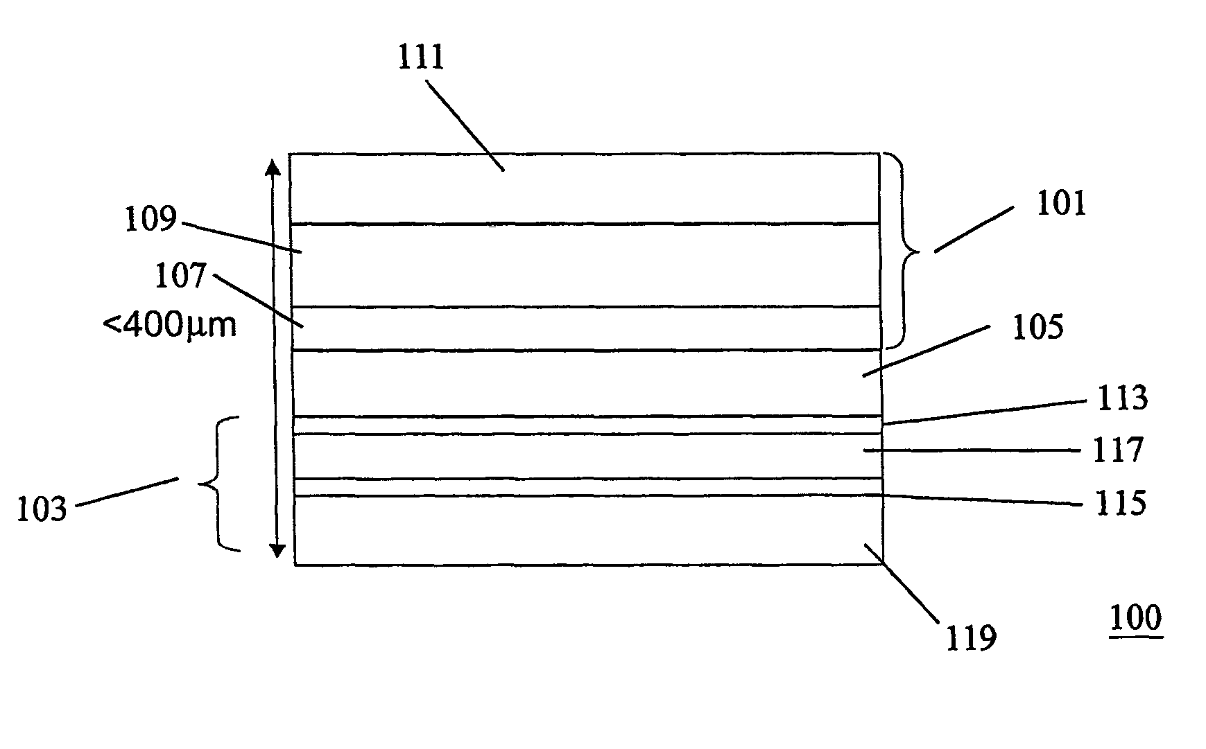
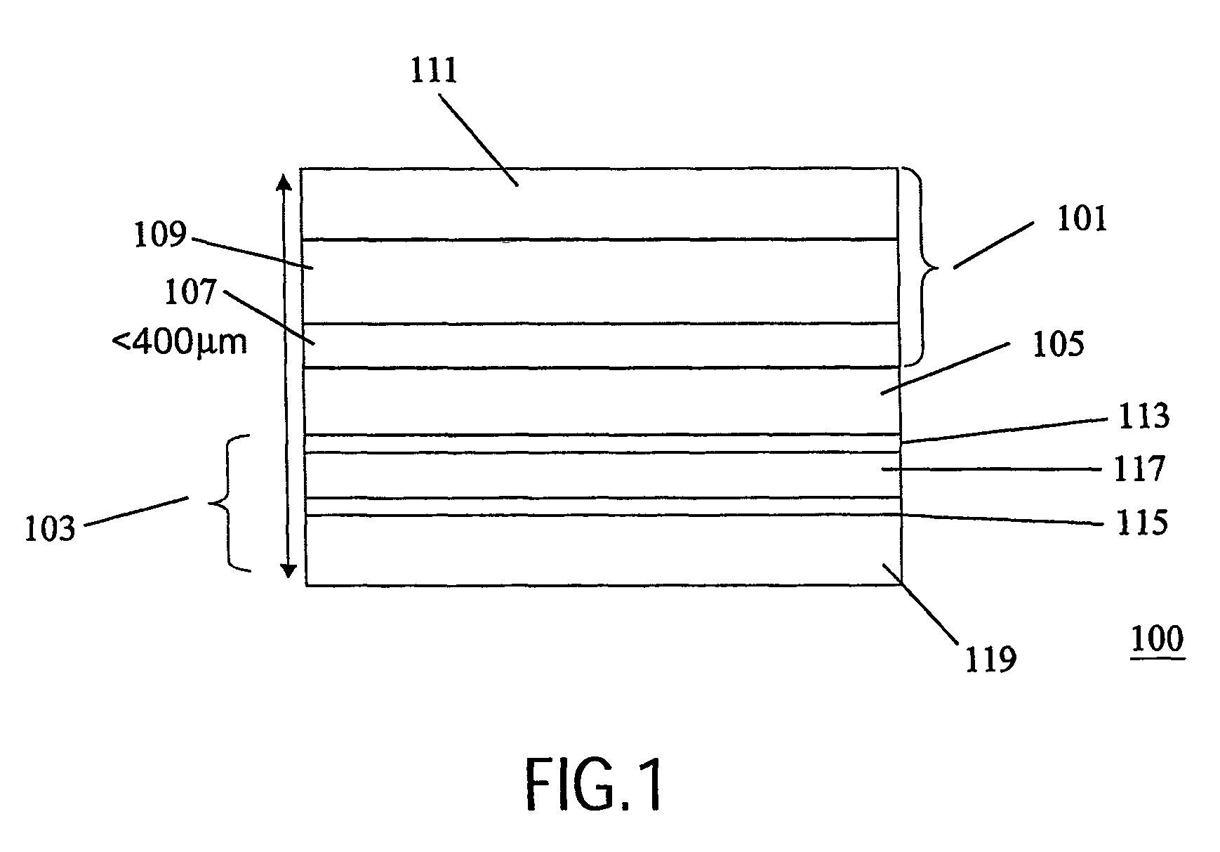
[0042]FIG. 1 illustrates a cross sectional view of a touch sensitive display 100 in accordance with a preferred embodiment of the invention.

[0043]The touch sensitive display 100 comprises an active matrix display element 101 and a touch sensitive element 103 separated by a passivation layer 105. In other embodiments the matrix display element 101 may be next to the touch sensitive element 103 or other and / or additional layers may be disposed between the matrix display element 101 and the touch sensitive element 103.

[0044]The active matrix display element 101 has a viewer proximal side and a viewer distal side. In FIG. 1, the viewer proximal sid...


PUM

PropertyMeasurementUnit
resistanceaaaaaaaaaa
electrical conductivityaaaaaaaaaa
pressureaaaaaaaaaa

Abstract

A portable device is provided having a touch sensitive display (100) comprising an active matrix display element (101) and a touch sensitive element (103). The touch sensitive element (103) is disposed on the viewer distal side of the active matrix display element (101) thereby not affecting the display properties. The touch sensitive element (103) comprises a first and second conductive layer (113, 115) each having a plurality of conductors. The conductive layers (113, 115) sandwich a pressure sensitive layer (117) which modifies an electrical conductivity between two conductors of the two conductive layers (113, 115) in response to a pressure point resulting from an applied pressure. Thus, accurate position detection is achieved. The conductors may be aligned with the active matrix and the requirement for calibration may be obviated.

Description

FIELD OF THE INVENTION[0001]The invention relates to a portable device and a touch sensitive display therefor and in particular to a touch sensitive display comprising an active matrix display element and a touch sensitive element.BACKGROUND OF THE INVENTION[0002]In recent years, there has been a general trend towards reduced size and increased mobility for many types of consumer equipment. For example, the use of portable phones, computers, personal music systems and personal digital Assistants (PDAs) have become increasingly widespread.[0003]The market for handheld and portable consumer electronics and computing has significantly diversified in the last decade. The trend has increasingly been towards smaller devices capable of displaying increasing amounts of information leading to improved displays having higher resolutions.[0004]In addition, the user interface has progressed significantly and much effort has been put into providing an intuitive interaction mechanism. A frequentl...

Claims


Application Information

Patent Timeline
Patent Type & Authority Patents(United States)
IPC IPC(8): G09G5/00G02F1/133G06F3/033G06F3/041G06K11/00G09F9/00G09G3/32
CPCG06F3/0412G06F3/0414G02F1/13338G06F3/04146G06F3/04144G06F3/04166
Inventor DESTURA, GALILEO JUNE ADEVAHUITEMA, HJALMAR EDZER AYCOVAN DELDEN, MARTINUS HERMANUS WILHELMUS MARIAVAN BEEK, JOZEF THOMAS MARTINUSKEMMEREN, ANTONIUS LUCIEN ADRIANUS MARIA
Owner SAMSUNG ELECTRONICS CO LTD
Why Eureka
Try Eureka