

Flexible fingerprint sensor arrays
Patent Information
- Authority / Receiving Office
- US · United States
- Current Assignee / Owner
- SHATFORD WILL
- Publication Date
- 2005-08-18
- Estimated Expiration
- Not applicable · inactive patent
Smart Images

Figure 1 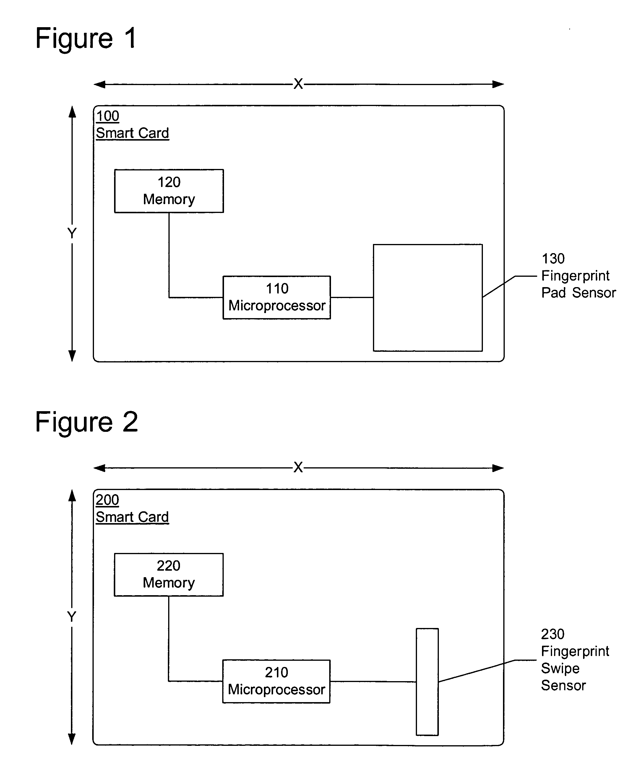
Figure 2 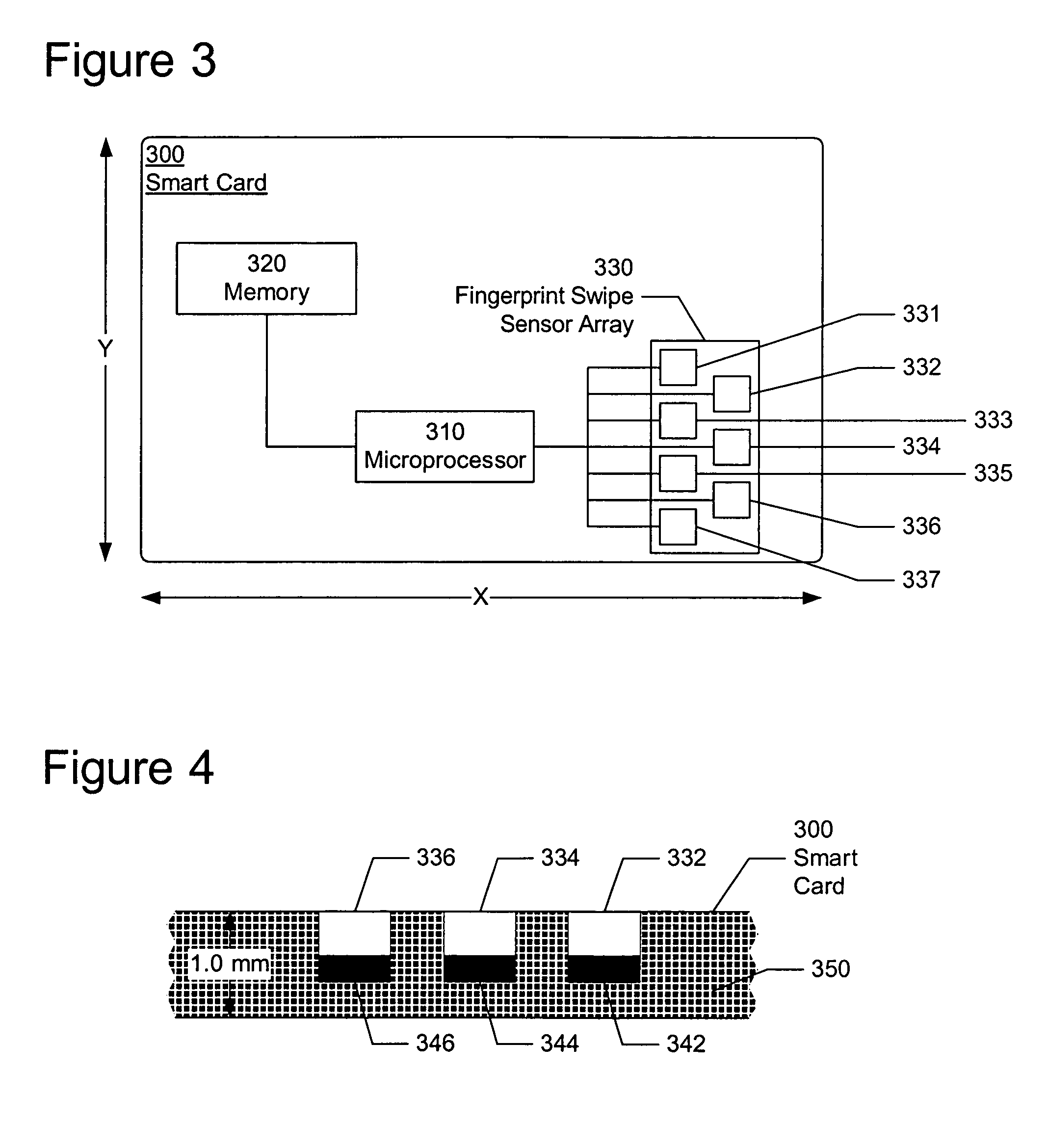
Figure 3
Abstract
Description
CROSS-REFERENCE TO A RELATED APPLICATION
[0001] This application for letters patent is related to and incorporates by reference provisional application Ser. No. 60 / 544,556, titled “Flexible Fingerprint Sensor Arrays,” and filed in the United States Patent and Trademark Office on Feb. 13, 2004.FIELD OF THE INVENTION
[0002] The present invention relates, in general, to biometric print scanning devices. In particular, the present invention is a fingerprint sensor constructed in an array configuration. BACKGROUND OF THE INVENTION
[0003] Computer security systems use biometric data, such as fingerprints, to authenticate the identity of the users attempting to gain access to a computer system. These computer systems include, but are not limited to, general-purpose computers such as desktop and portable personal computers, peripheral devices that connect to a general-purpose computer, and mobile devices such as credit cards, smart cards, cellular telephones, satellite telephones, and porta...