Diesel electric locomotive

Inactive Publication Date: 2005-08-25
SIEMENS AG
View PDF2 Cites 10 Cited by
  • Summary
  • Abstract
  • Description
  • Claims
  • Application Information

AI Technical Summary

Benefits of technology

[0019] The diesel electric locomotive according to an embodiment of the invention achieves the advantage that the auxiliary appliances can be supplied with electrical power even when the d

Problems solved by technology

A further disadvantage is that the auxiliary appliances cannot be supplied if the auxiliary generator fails.
In this

Method used


Image

  • Diesel electric locomotive
  • Diesel electric locomotive
  • Diesel electric locomotive

Examples


Embodiment Construction

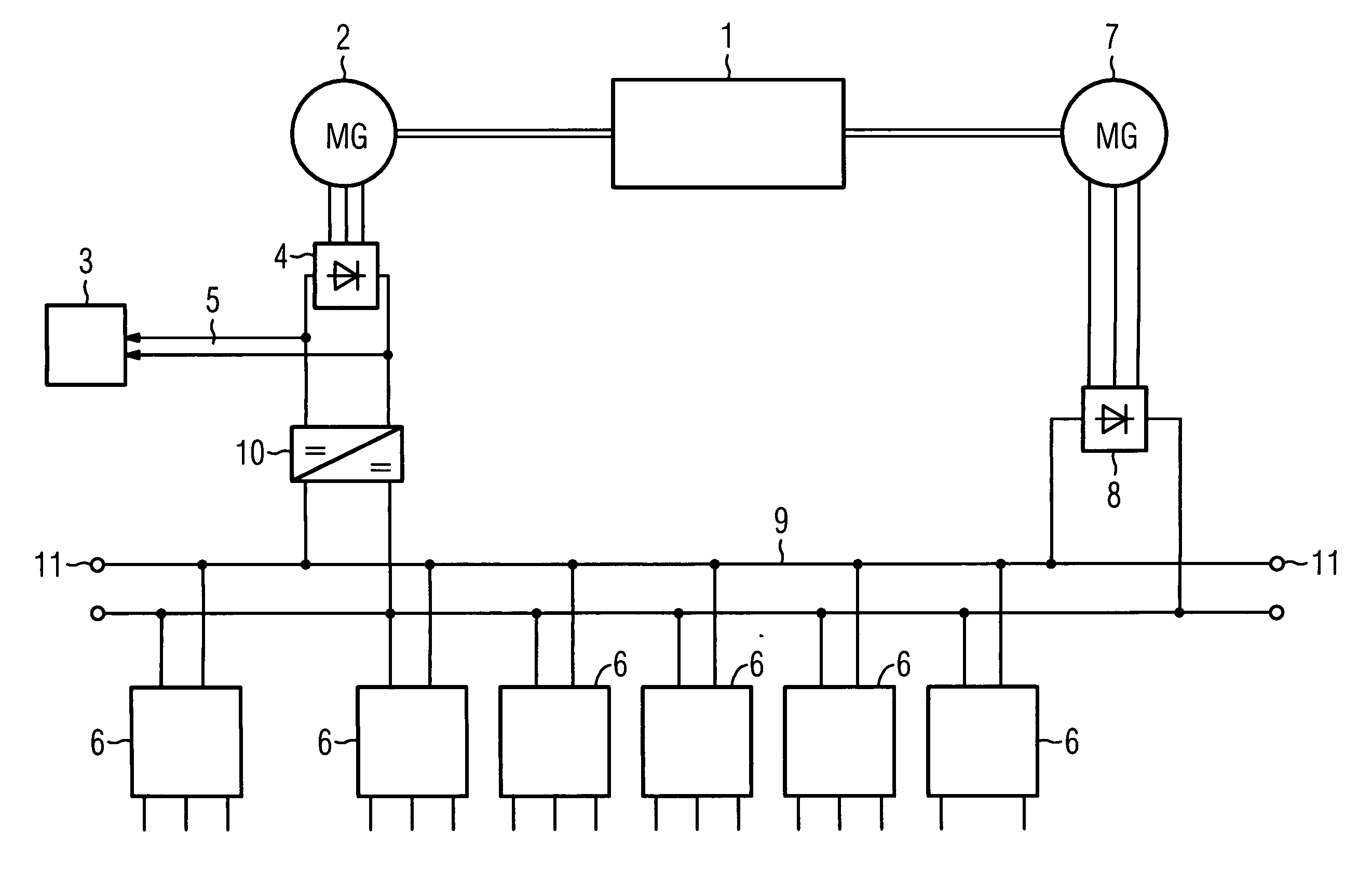
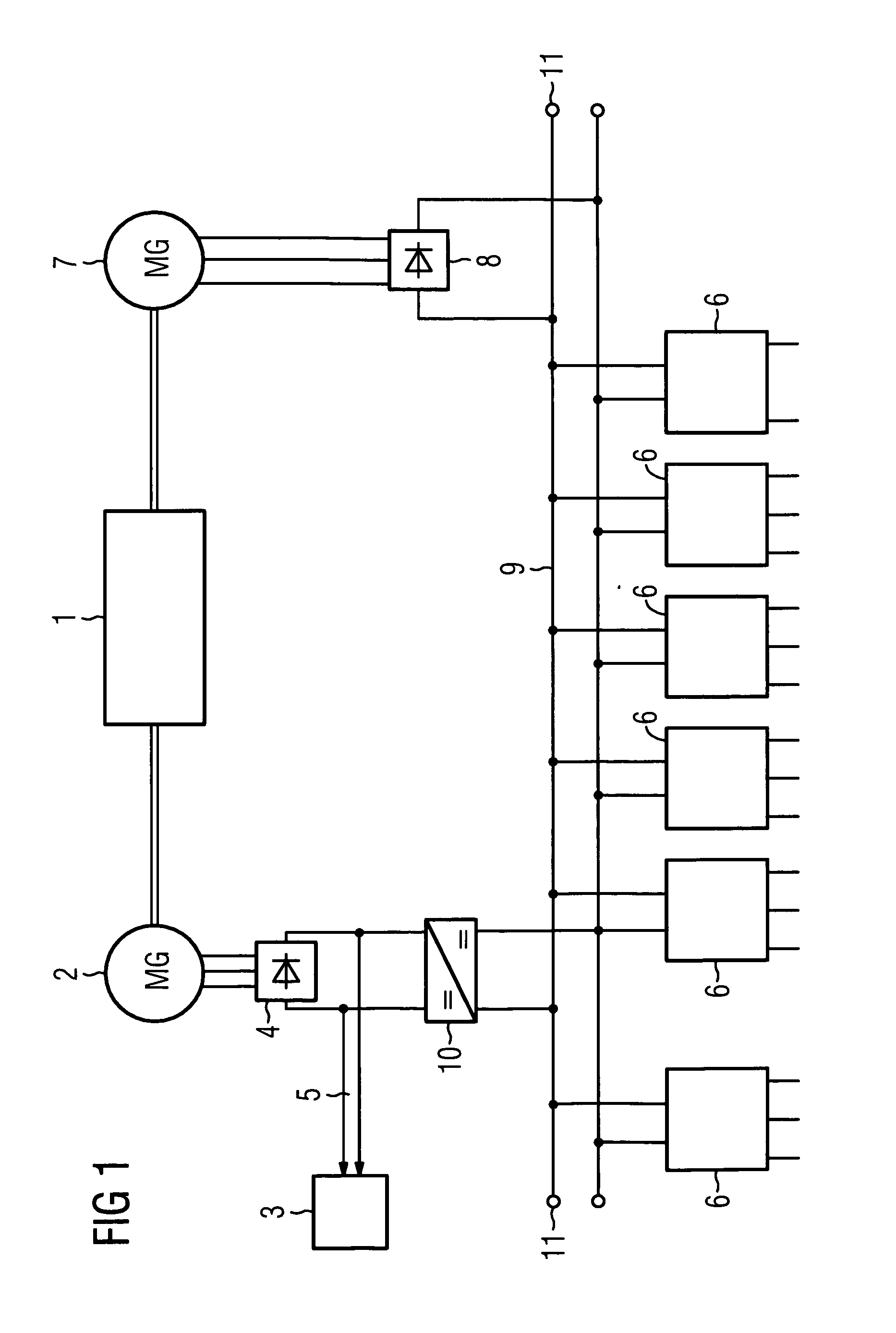
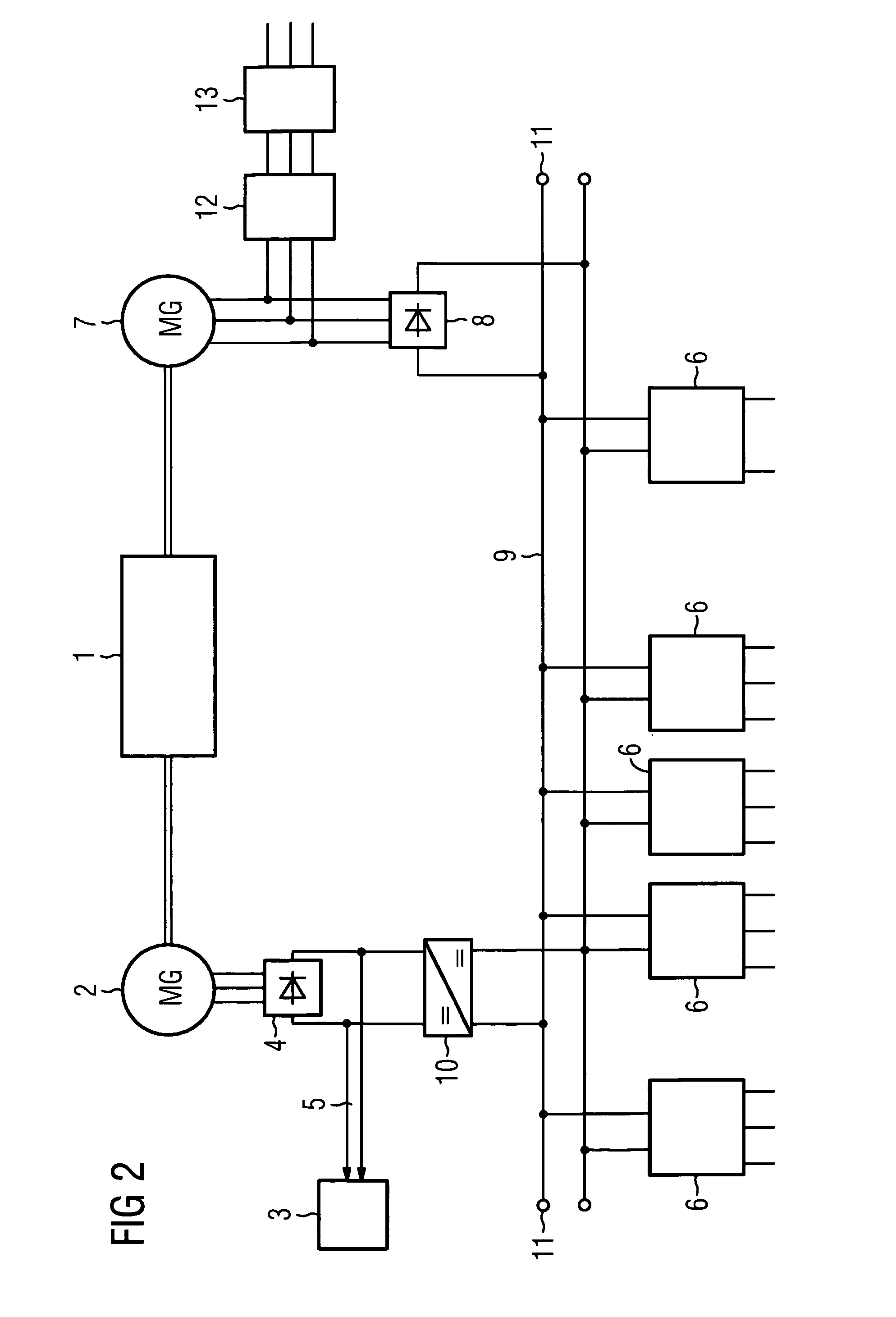
[0023] In both FIG. 1 and FIG. 2, a diesel engine 1 in a diesel electric locomotive is connected to a main generator 2. This is used for operation of the drive apparatus 3 and is for this purpose connected via a first rectifier 4 to a direct current traction intermediate circuit 5, to which the drive apparatus 3 is connected. The drive apparatus 3 has a converter and a motor.

[0024] The diesel engine 1 is also connected to an auxiliary generator 7 in order to operate various auxiliary appliances 6 which, by way of example, may be fans or heaters. This auxiliary generator 7 is electrically connected via a second rectifier 8 to a direct current auxiliary operation intermediate circuit 9, to which the auxiliary appliances 6, the upstream components, such as converters by way of example, are connected.

[0025] In order to allow the auxiliary appliances 6 to be supplied with electrical power even when the auxiliary generator 7 is not in operation, the first rectifier 4, which is connected...


PUM


Abstract

A diesel electric locomotive includes a main generator for a drive apparatus and an auxiliary generator for auxiliary appliances, connected to a diesel engine. The main generator is connected by a first rectifier to the direct current traction intermediate circuit of the drive apparatus. The auxiliary generator is connected via a second rectifier to a direct current auxiliary operation intermediate circuit of the auxiliary appliances. The main generator is likewise connected via the rectifier and a DC/DC converter to the direct current auxiliary operation intermediate circuit.

Description

[0001] The present application hereby claims priority under 35 U.S.C. §119 on German patent application numbers DE 10 2004 008 485.8 filed Feb. 20, 2004, the entire contents of which is hereby incorporated herein by reference. FIELD OF THE INVENTION [0002] The invention generally relates to a diesel electric locomotive. Preferably, it relates to one in which a main generator for a drive apparatus and an auxiliary generator for auxiliary appliances are connected to a diesel engine, and / or in which the main generator is connected via a first rectifier to the direct current traction intermediate circuit of the drive apparatus. BACKGROUND OF THE INVENTION [0003] DE 42 17 303 A1 discloses a fan unit which is supplied from an auxiliary operation power supply system. The fan unit is used for cooling a diesel engine in a diesel electric locomotive. An auxiliary generator is used to supply electrical power to the auxiliary operation power supply system. The fan unit is driven by a motor. [00...

Claims


Application Information

Patent Timeline
IPC IPC(8): B60L50/10B60L50/13B61C1/00
CPCB60L11/08B60L2210/10Y02T10/70B60L2200/26Y02T10/7216B60L50/13Y02T10/72
Inventor GRITSCH, CHRISTIAN
Owner SIEMENS AG
Why Eureka
Try Eureka