
Hybrid vehicle, control method for hybrid vehicle, and controller for hybrid vehicle

a hybrid vehicle and control method technology, applied in the direction of engine-driven generators, machines/engines, electric devices, etc., can solve the problems of insufficient electric power supply and it is difficult to supply electric power stably to the electric device outside the vehicl

Active Publication Date: 2017-10-24
TOYOTA JIDOSHA KK
View PDF18 Cites 2 Cited by
  • Summary
  • Abstract
  • Description
  • Claims
  • Application Information

AI Technical Summary

Benefits of technology

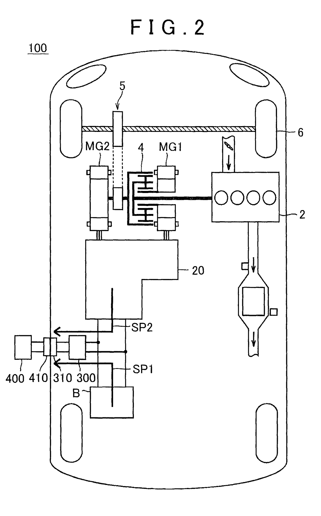
[0010]According to this configuration, electric power can be supplied from the electric storage device to the electric device only for a necessary period that has been preliminarily determined in view of the shortage of the generated electric power at the start of the internal combustion engine. Thus, over-discharge of the electric storage device can be prevented.
[0012]According to this configuration, an excessive supply of electric power from the electric storage device can be prevented. As a result, the power input and output of the electric storage device can be reduced and the electricity efficiency can be improved.
[0016]According to this configuration, the individual peculiarities of the internal combustion engine, the changes of the internal combustion engine with the passage of time, or the changes in output from the internal combustion engine depending on the operating environment can be detected. Thus, the shortage of generated electric power can be detected precisely.
[0023]According to the invention, it is possible to provide a hybrid vehicle that can supply electric power stably to an electric device outside the vehicle and a control method for the hybrid vehicle.

Problems solved by technology

However, immediately after the engine is started, a sufficient electric power supply may not be provided to the electric device outside the vehicle because of a delay in response of engine torque.
At this time, it is difficult to supply electric power stably to the electric device outside the vehicle because of shortage of electric power that can be supplied to the electric device outside the vehicle.

Method used


Image

  • Hybrid vehicle, control method for hybrid vehicle, and controller for hybrid vehicle
  • Hybrid vehicle, control method for hybrid vehicle, and controller for hybrid vehicle
  • Hybrid vehicle, control method for hybrid vehicle, and controller for hybrid vehicle

Examples


Embodiment Construction

[0029]An embodiment of the present invention is hereinafter described in detail with reference to the drawings. The same or corresponding parts are designated by the same reference numerals in all the drawings and their description is not repeated.

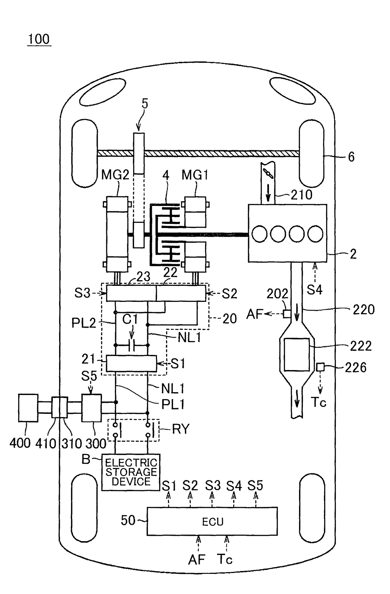
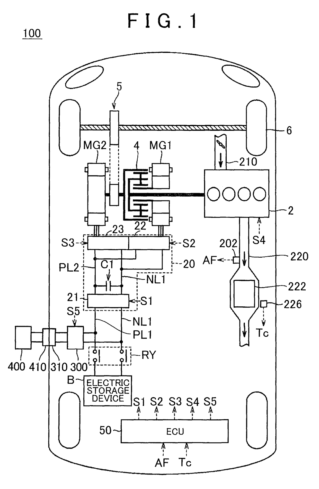
[0030]FIG. 1 is a block diagram that illustrates the general configuration of a hybrid vehicle according to an embodiment of the present invention. Referring to FIG. 1, a hybrid vehicle 100 includes an engine 2, motor generators MG1 and MG2, a power split device 4, a reduction gear 5, driving wheels 6, an electric storage device B, a PCU (Power Control Unit) 20, and a controller (which may be hereinafter also referred to as “ECU (Electronic Control Unit”) 50.

[0031]The engine 2 is an internal combustion engine that generates driving force for rotating a crankshaft by combustion energy that is produced by combusting a mixture of air and fuel that is drawn into its combustion chambers. The motor generators MG1 and MG2 are AC electric motors, ...


PUM


Abstract

A hybrid vehicle includes an internal combustion engine, a rotating electric machine, an electric storage device, a power supply device, and a controller. The controller executes switching control to switch from a first electric power supply to a second electric power supply by starting the internal combustion engine. The first electric power supply is the supply of electric power from the electric storage device to the electric device. The second electric power supply is the supply of electric power from the rotating electric machine to the electric device. The controller controls the power supply device and the internal combustion engine such that the internal combustion engine is started with the first electric power supply being continued during the switching control.

Description

BACKGROUND OF THE INVENTION[0001]1. Field of the Invention[0002]The present invention relates to a hybrid vehicle, a control method for a hybrid vehicle, and a controller for a hybrid vehicle. More specifically, the present invention relates to a hybrid vehicle that can supply electric power to an electric device outside the vehicle, a control method for the hybrid vehicle, and a controller for the hybrid vehicle.[0003]2. Description of Related Art[0004]Japanese Patent Application Publication No. 2007-236023 (JP 2007-236023 A) discloses a hybrid vehicle that can supply electric power to an electric device outside the vehicle. The hybrid vehicle selects, when a power supply connector is connected thereto, whether to supply electric power that has been stored in a battery to an electric device outside the vehicle or to supply electric power that is generated using the driving force of the engine to an electric device outside the vehicle based on the remaining battery level.[0005]When ...

Claims


Application Information

Patent Timeline
Patent Type & Authority Patents(United States)
IPC IPC(8): B60W10/06B60W10/08B60W10/26B60W30/18B60W20/10B60L3/00B60L3/04B60L7/14B60L11/12B60L11/14B60L11/18B60L15/20B60K6/24B60K6/28B60K6/365B60K6/40F02P3/09B60K6/26B60W20/40F02B25/12B60L50/15B60L50/16
CPCB60W20/40B60K6/24B60K6/26B60K6/28B60K6/365B60K6/40B60L3/0046B60L3/04B60L7/14B60L11/123B60L11/14B60L11/1816B60L11/1842B60L11/1844B60L11/1846B60L11/1859B60L15/20B60L15/2009B60L15/2054B60W10/06B60W10/08B60W10/26B60W20/10B60W30/18054B60K2006/268B60L2210/10B60L2210/40B60L2240/12B60L2240/36B60L2240/421B60L2240/423B60L2240/441B60L2240/443B60L2240/445B60L2240/486B60L2240/80B60L2260/26B60L2270/12B60L2270/145B60W2710/06B60W2710/242B60Y2200/92Y02E60/721Y02T10/6217Y02T10/6286Y02T10/645Y02T10/705Y02T10/7005Y02T10/7072Y02T10/7077Y02T10/7216Y02T10/7241Y02T10/7275Y02T90/121Y02T90/127Y02T90/128Y02T90/14Y02T90/163Y02T90/169Y04S10/126Y04S30/14Y10S903/905Y10S903/906Y10S903/907Y10S903/91Y10S903/93Y10S903/951B60L50/61B60L50/16B60L55/00B60L53/63B60L53/65B60L58/15Y02E60/00Y02T10/62Y02T10/64Y02T10/72Y02T10/70Y02T90/12Y02T90/167Y02T90/16
Inventor INOUE, TOSHIOFUSHIKI, SHUNSUKEHONDA, TOMOAKIFUKUI, KEITANAWATA, HIDEKAZUNIWA, YUTAOHSAWA, TAICHI
Owner TOYOTA JIDOSHA KK
Learn More