Turbocharger of variable turbine geometry

a variable turbine and turbine geometry technology, applied in liquid fuel engines, machines/engines, lighting and heating apparatus, etc., can solve problems such as dislocation of disks and vanes jamming, and achieve the effect of keeping the energy input to the disk as small

Active Publication Date: 2006-06-29
BORGWARNER INC
View PDF5 Cites 19 Cited by
  • Summary
  • Abstract
  • Description
  • Claims
  • Application Information

AI Technical Summary

Benefits of technology

[0008] Thanks to the provision of such a heat throttle, the energy input into the disk can be kept as small as possible. Another advantage of said heat throttle must be seen in the fact that since less energy is discharged into the material of the disk which surrounds the welded joint, i.e. the energy remains “trapped” at the welded joint, less welding energy is needed on the whole for welding the disk material.

Problems solved by technology

Welding, however, may distort the disk due to rigid heat introduction.
A distortion of the disk may lead to a jamming of the vanes due to the gap reduction which is locally caused thereby between vanes and disk.

Method used


Image

  • Turbocharger of variable turbine geometry
  • Turbocharger of variable turbine geometry
  • Turbocharger of variable turbine geometry

Examples


Embodiment Construction

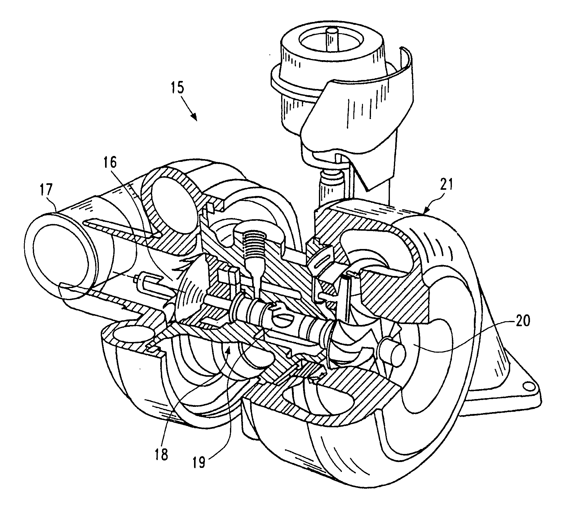
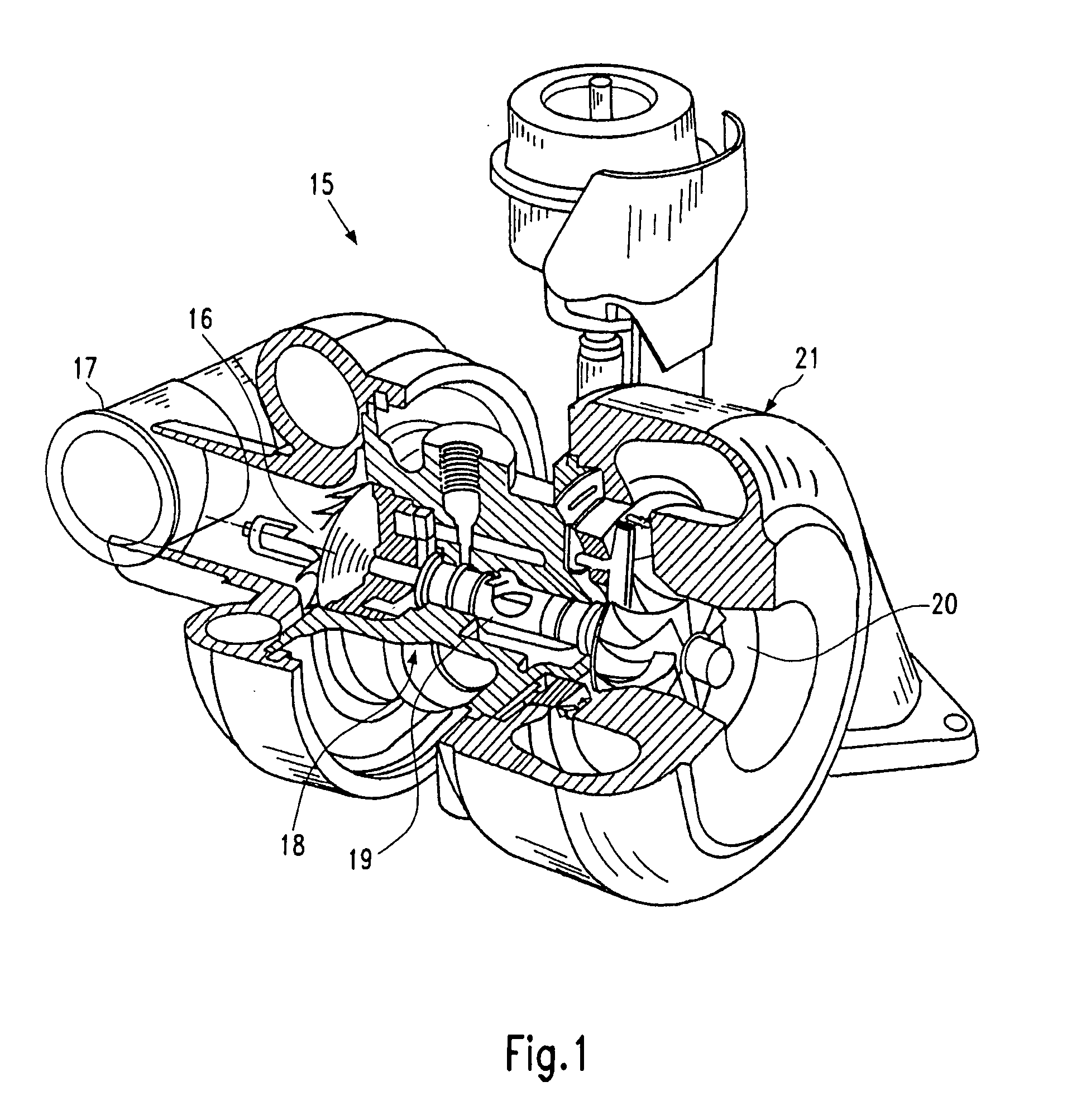
[0015] Since a complete illustration of all constructional details of a turbocharger of variable turbine geometry is not needed for the following description of the constructional principles of the invention, FIG. 1 only shows the basic components of a turbocharger 15 according to the invention, the turbocharger 15 comprising a compressor impeller 16 in a compressor housing 17, a bearing housing 18 with the necessary bearings for the shaft 19, and a turbine wheel 20 in a turbine casing 21 in the standard manner. The remaining parts are not needed for explaining the present invention for illustrating all of the principles thereof, but said parts are of course provided.

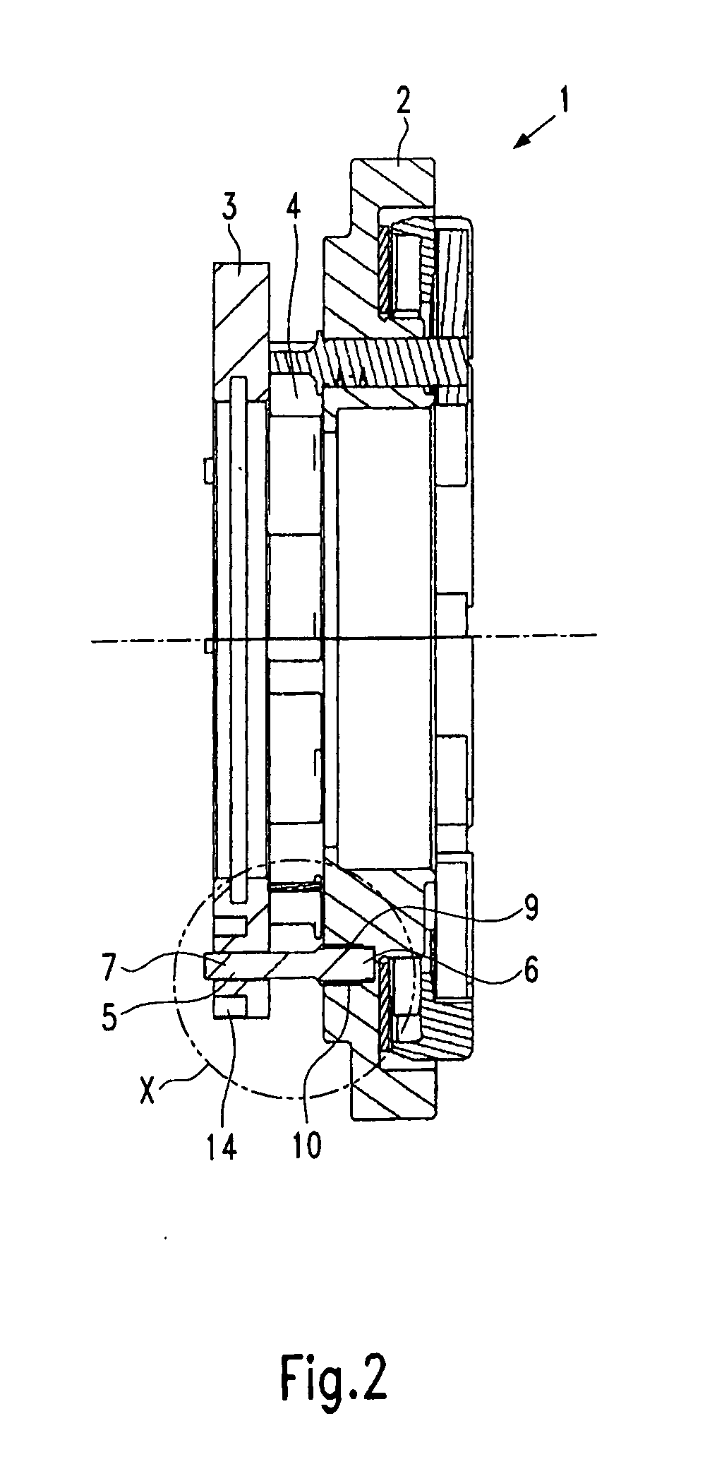
[0016] Hence, FIG. 2 only shows a vane bearing assembly 1 of a turbocharger according to the invention. The vane bearing assembly 1 comprises a vane bearing ring 2 on which a disk 3 is arranged at a defined distance. The disk 3 is preferably made from the same material as the vane bearing ring 2 and serves, as has been...


PUM


Abstract

A turbocharger of variable turbine geometry, comprising: a vane bearing ring assembly including a vane bearing ring and a disk which can be fixed to the vane bearing ring for creating a flow channel; and at least one support pin which is connected with a first end to the vane bearing ring and which is welded with a second end to the disk which comprises recesses for the support pin end to be welded, said recesses being surrounded by a heat throttle.

Description

CROSS-REFERENCE TO RELATED APPLICATIONS [0001] This application claims priority to European Patent Application No. 04030888.4 filed Dec. 28, 2004. FIELD OF THE INVENTION [0002] The present invention relates to a turbocharger of variable turbine geometry (VTG). BACKGROUND OF THE INVENTION [0003] The VTG cartridge of such a turbocharger as known from EP 1 236 866 A consists of a guide apparatus comprising vanes and levers and a disk at the turbine casing side. The disk is fixed to a vane bearing ring of a vane bearing assembly in generic turbochargers by means of screws or by welding. To be able to set a defined width for the flow channel which is formed between vane bearing ring and disk and in which the vanes of VTG are positioned, spacer sleeves are needed which in the case of a welded joint can be removed again after welding. Welding, however, may distort the disk due to rigid heat introduction. A distortion of the disk may lead to a jamming of the vanes due to the gap reduction w...

Claims


Application Information

Patent Timeline
Patent Type & Authority Applications(United States)
IPC IPC(8): F04D29/56
CPCF01D17/165F05D2220/40F05D2230/30F05D2260/231F02B37/22F01D17/04
Inventor BOENING, RALFMETZ, DIETMARFRANKENSTEIN, DIRK
Owner BORGWARNER INC
Why Eureka
Try Eureka