Method for the production of an insulating profile

a technology of insulating profiles and profiles, which is applied in the field of insulating profiles, can solve the problems of high tooling costs, inability to simply increase the visible width of metal-plastic composites, and inability to react to particulars, etc., and achieves low energy input, high output speed, and high dimensional accuracy.

Active Publication Date: 2020-04-09
ENSINGER
View PDF0 Cites 2 Cited by
  • Summary
  • Abstract
  • Description
  • Claims
  • Application Information

AI Technical Summary

Benefits of technology

[0022]Amongst other things, methods for welding endless or sheet materials by means of ultrasonics are widespread in the consumer goods industry and are employed in, e.g., the production of diapers, plastic bags or blister packs. Hereby, plastic films of very low thickness are usually used as so-called joining partners which are then welded in-line with the aid of roller sonotrodes or (accompanying) clocked sonotrode stampers. These welding processes are not however suitable for producing plastics parts having thicknesses in the millimeter range, e.g., insulating bars, with high output speeds and high dimensional accuracy. Problematic above all in the case of the known ultrasonic welding processes is the relatively small energy input of roller sonotrodes due to the very small effective contact area of a sonotrode (this results from the radius of a sonotrode roller) or the large amount of deformation of the products at the offset locations when using clocked stamping sonotrodes.
[0116]Insulating profiles produced in accordance with the method in accordance with the invention can be identified accurately. Suitable methods for the analysis are, for example, optical microscopy of the micrograph or the insulating profile itself. Likewise, thermal analyses of the joining zone are possible. Characteristic hereby, are the mass or flow of the smelt in the region of the joining zone, indications of the type of plasticizing process, indications of the location and the type of energy input, indications of the type of guidance of the profiles, indications of the form, geometry and composition of the joining partners.

Problems solved by technology

Apart from the high tooling costs, a further disadvantage of this classical method is the missing flexibility on the part of the manufacturer to be able to react to particular requests for alterations in regard to adaptations of the geometry of the composite.
Thus for example, one cannot simply increase the visible width of the metal-plastics composite while maintaining the insulating profile without losing out on the insulating effect.

Method used


Image

  • Method for the production of an insulating profile
  • Method for the production of an insulating profile
  • Method for the production of an insulating profile

Examples


first embodiment

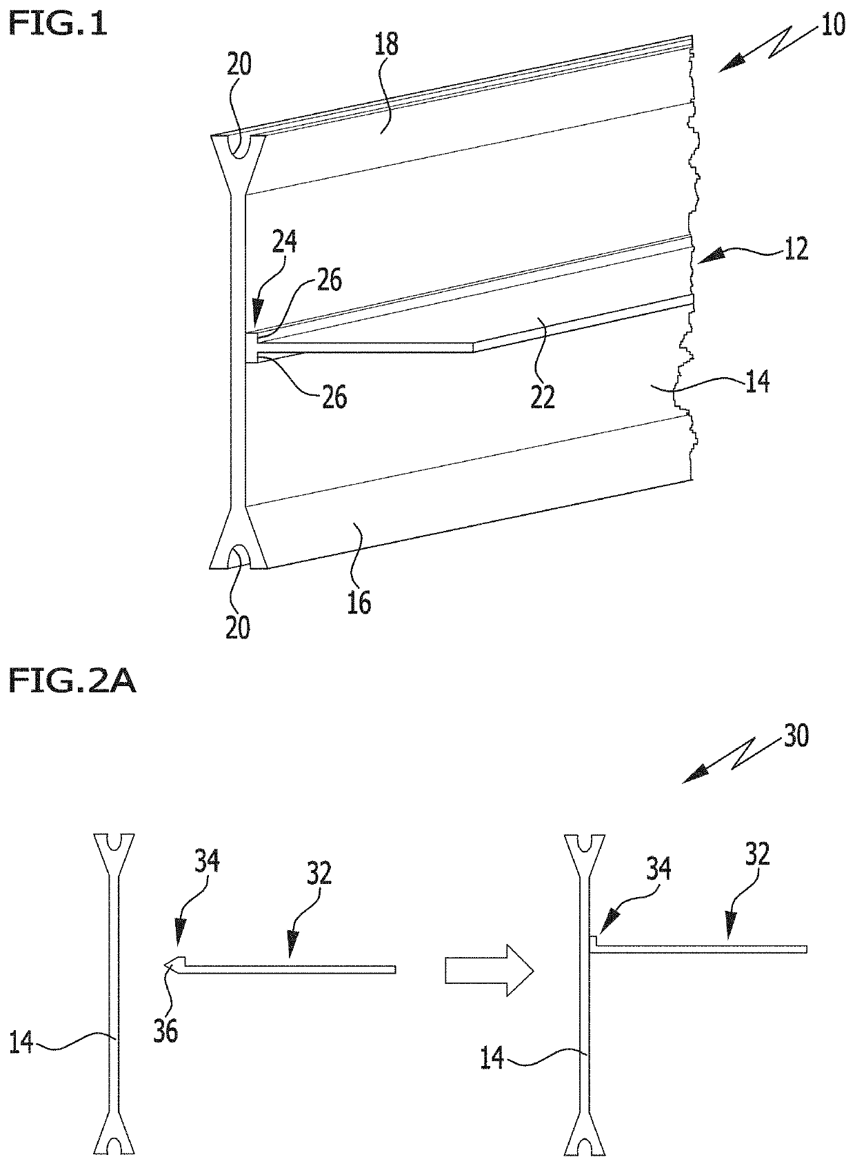
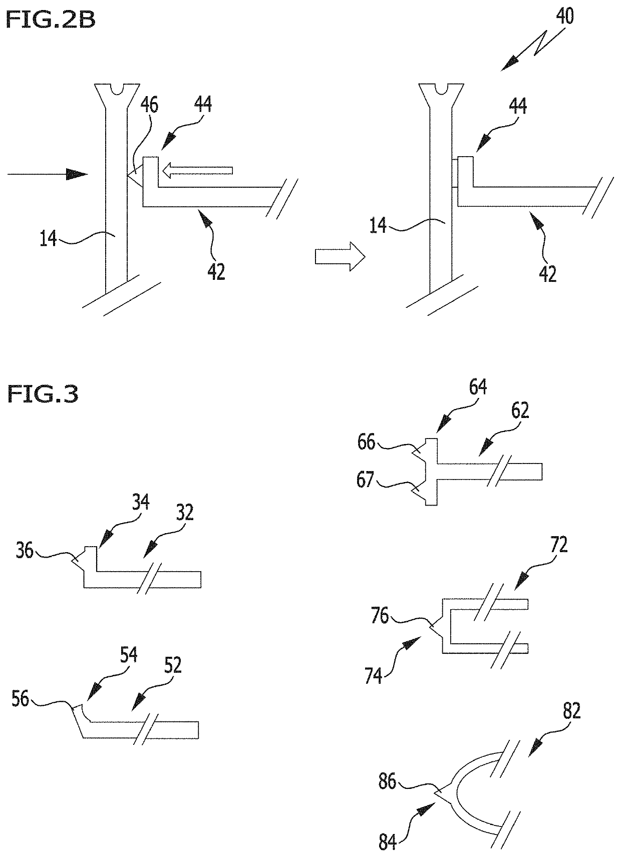
[0105]In a first embodiment, the introduction of the energy is preferably effected by a static sonotrode which is implemented, e.g., in the form of a grinding sonotrode with substantially rectangular contact areas, or in the form of a contact skid or a block sonotrode, a slotted block sonotrode, a cutting sonotrode, a double cutting-edge sonotrode, the joining partners or the joining partners is / are then usually fed past it in permanent contact with the sonotrode.

[0106]A person skilled in the art can adopt the commonly available measures for minimizing the wear on the sonotrode due to the permanent and intensive frictional and sliding contact with the polymer materials being used and, if necessary, to also reduce the friction itself.

[0107]The contact pressure is effective from the sonotrode via the joining partners to an opposing stop or an anvil. This anvil can be designed in the form of rollers, contact skids, or as a rigid block or the like for example.

[0108]The positioning of th...

embodiment 1

[0122]2. A method in accordance with embodiment 1, wherein the profile body and the first functional element are supplied continuously or intermittently to the ultrasonic welding device.

[0123]3. A method in accordance with embodiment 1 or 2, wherein the profile body and / or the first functional element are provided in the form of a continuous material or in lengths.

[0124]4. A method according to any of the embodiments 1 to 3, wherein, before going through the welding zone, the profile body and the functional element are positioned relative to each other by means of a first guidance device in a predetermined, optionally variable relative position and fed in the longitudinal direction.

[0125]5. A method according to any of the embodiments 1 to 4, wherein, after going through the welding zone, the profile body and the functional element are positioned relative to each other in a predetermined, optionally variable position by means of a second guidance device and fed in the longitudinal d...

embodiment 18

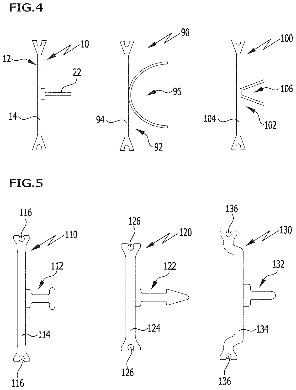
[0139]19. A method in accordance with embodiment 18, wherein the functional element is provided neighboring the projection or the projections with one or more stop elements which defines / define the cross-sectional geometry that is sought when the functional element and the profile body are brought together, wherein the projection or the projections is / are formed with the function as shoulders.

[0140]20. A method according to any of the embodiments 1 to 19, characterized in that the connection between the first functional element or the first functional elements and the profile body by a material bond is effected along the longitudinal direction of the insulating profile continuously, in sections or in point-like manner.

[0141]21. A method according to any of the embodiments 1 to 20, wherein, apart from the profile body, the functional elements are also provided in the form of continuous material and, after the production of the connection thereof by a material bond, the insulating pro...


PUM

PropertyMeasurementUnit
lengthaaaaaaaaaa
lengthaaaaaaaaaa
temperatureaaaaaaaaaa

Abstract

A method for producing insulating profiles comprises manufacturing a profile body and a first functional element separately, and the profile body and the first functional element are supplied to an ultrasonic welding device, wherein the profile body and the functional element are connected to one another by a material bond by formation of a welded joint. The profile body and the functional element are brought together into a predetermined first cross-sectional geometry during formation of the welded joint and are thereafter guided in this cross-sectional geometry until the plastics material of the welded joint solidifies to such an extent that the profile body and the first functional element are fixed in the predetermined cross-sectional geometry.

Description

CROSS-REFERENCE TO RELATED APPLICATIONS[0001]This patent application claims the benefit under 35 USC 119(b) of German application No. 10 2018 124 779.6, filed Oct. 8, 2018, which is incorporated by reference.BACKGROUND OF THE INVENTION[0002]The invention relates to a method for the production of an insulating profile, in particular, for the production of window, door and facade components and also to the insulating profiles produced by the method. The insulating profile that is to be manufactured comprises an insulating bar manufactured from a first polymer material which comprises a profile body as well as a first functional element which both extend in the longitudinal direction of the insulating profile, wherein the first functional element is connected to the insulating bar in a contact region by a material bond.[0003]In particular, the insulating profiles mentioned hereinabove are employed in diverse manners for the production of metal-plastics composite profiles wherein the in...

Claims


Application Information

Patent Timeline
Patent Type & Authority Applications(United States)
IPC IPC(8): E06B3/273B29C65/08E06B3/263
CPCE06B3/273B29C65/08E06B3/26305B29C65/44B29C65/7858B29C66/47B29C66/742B29C66/9131E06B3/263B29L2031/005E06B2003/26325B29C65/8253B29C66/81431B29C66/131B29C66/112B29C66/3022B29C66/52441B29C66/712B29C66/7461B29C66/232B29C66/1122B29C66/118B29C66/73921B29C66/7392B29C65/7829B29C65/7873B29C66/836B29C66/322B29C65/8215B29C66/721B29C66/7212B29C66/71B29C66/81425B29C66/81419B29C66/81465B29C66/81415B29C65/081B29K2309/08B29K2077/00B29K2067/00B29K2023/00B29K2071/00B29K2069/00B29K2081/04
Inventor KARL, CHRISTOPHWEISSTHANNER, WILLIMÖLLER, MICHAEL
Owner ENSINGER
Why Eureka
Try Eureka