Shaft drive for heald shafts of weaving machines

a technology of weaving machine and shaft drive, which is applied in the direction of looms, dollies, textiles and papermaking, etc., can solve the problems of inflexible eccentric machines and limited production of patterns or various textures, and achieve the effect of rapid respons

Inactive Publication Date: 2009-01-13
GROZ BECKERT KG
View PDF43 Cites 2 Cited by
  • Summary
  • Abstract
  • Description
  • Claims
  • Application Information

AI Technical Summary

Benefits of technology

[0008]The switching pawl is engaged and disengaged by an actuating device. The latter is, for example, a slider which may be displaced between two positions. The switching pawl passes by the slider and is actuated according to the slider position. The actuating device may also be formed by at least one, but preferably by two switching levers. The switching pawl passes by the switching levers and is thus actuated (for example, engaged) thereby. For the temporary connection of the actuating device with the switching pawl, preferably a slot guide is proved. The latter ensures that the moving switching pawl, for example, revolving together with the driven disk, may be displaced freely in the circumferential direction and further, the slot guide transmits the radially directed switching motion to the switching pawl.
[0009]The slider may be actuated by a driven rotary cam with which the slider is in contact by means of a cam follower. The switching levers may be actuated directly by electrical or pneumatic means. It is, however, preferred to drive the switching levers from a cam drive with the intermediary of a control clutch. The latter may be operated with very little power, while sufficiently large forces are generated for moving the switching levers. The switching clutch may be controlled, for example, by stationary or movable control magnets and may be formed by an oscillatingly driven selector finger. Such an arrangement results in an accurately responding clutch control device which may be controlled with small energy input.
[0014]In a particularly advantageous embodiment of the invention two mutually separated switching pawls are provided. In this manner a first switching pawl may be associated with the first driving disk and the second switching pawl may be associated with the second driving disk. In this arrangement the switching pawls are preferably disposed at diametrically opposite sides of the driven disk. The switching pawls may be resiliently biased toward their engagement position or, as described earlier, they may be connected with a bi-stabile biasing device having the earlier-noted advantages. The embodiment having two switching pawls has the advantage that the switching motions of a respective switching pawl may be set to be independent from the switching motions of the other switching pawl. This too, is of advantage for obtaining reliable higher operating and switching speeds.
[0017]Preferably, the drive imparts on the heald shaft a continuing motion not only during its motion phases, but also during its resting phases in which, in conventional arrangements, the heald shaft is at a standstill in the upper or lower point of reversal. This offers the possibility to reduce the maximum accelerations of the heald shaft. The avoidance of abrupt acceleration increases leads to a shock-free run of the heald shafts. Such a run, even at high working speeds, does not lead to excessive excitation of oscillations. The limit for the working speed in which heald shaft breakages and heald breakages occur, may thus be shifted to significantly higher working speeds.

Problems solved by technology

However, such eccentric machines are inflexible.
The production of patterns or various textures is feasible only in a limited manner.

Method used


Image

  • Shaft drive for heald shafts of weaving machines
  • Shaft drive for heald shafts of weaving machines
  • Shaft drive for heald shafts of weaving machines

Examples


Embodiment Construction

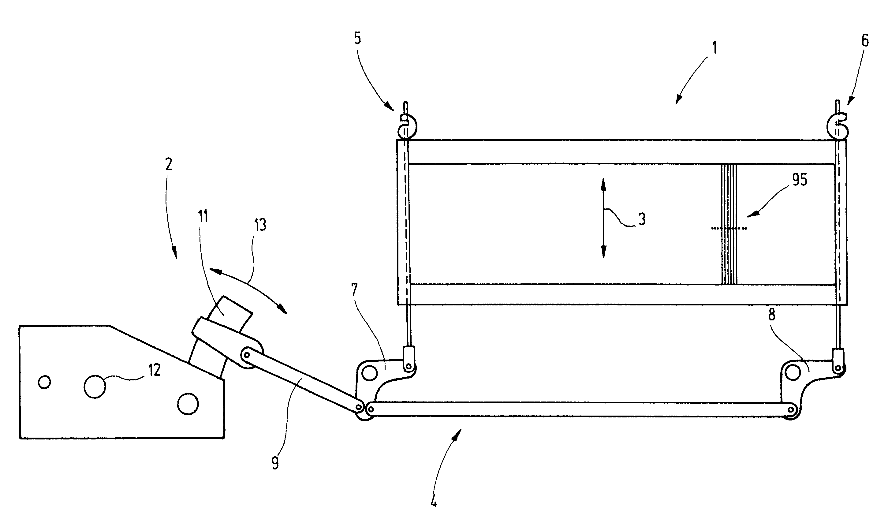
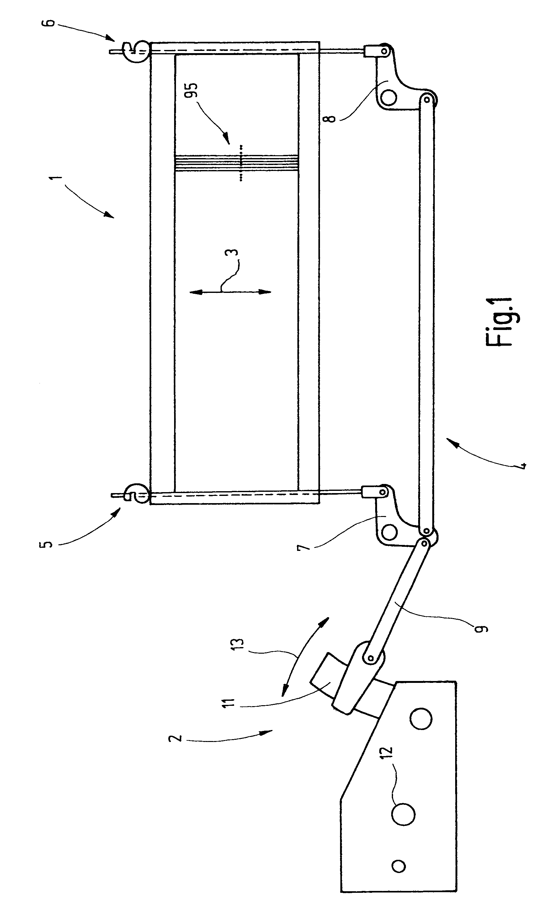
[0032]FIG. 1 shows a heald shaft 1 and a shaft drive 2 associated therewith. The heald shaft 1 is formed by a frame which is provided with healds 95 and which is reciprocated up and down as indicated by an arrow 3. For driving the heald shaft 1, a linkage 4 is provided which is connected to the heald shaft 1 at two or more locations 5, 6 and which constitutes the driven mechanism of the shaft drive 2. The linkage 4 comprises bell crank levers 7, 8 which are connected, on the one hand, with the heald shaft 1 and, on the other hand, directly or indirectly with a push-pull rod 9. The latter is coupled to the shaft drive 2 which, for this purpose, has, at its output, a rocker arm 11 which executes an oscillating motion. The shaft drive 2 generates from the uniform rotary motion of an input shaft 12 the back-and-forth motion designated by an arrow 13. This motion imparts to the heald shaft 1 a substantially harmonic oscillating motion.

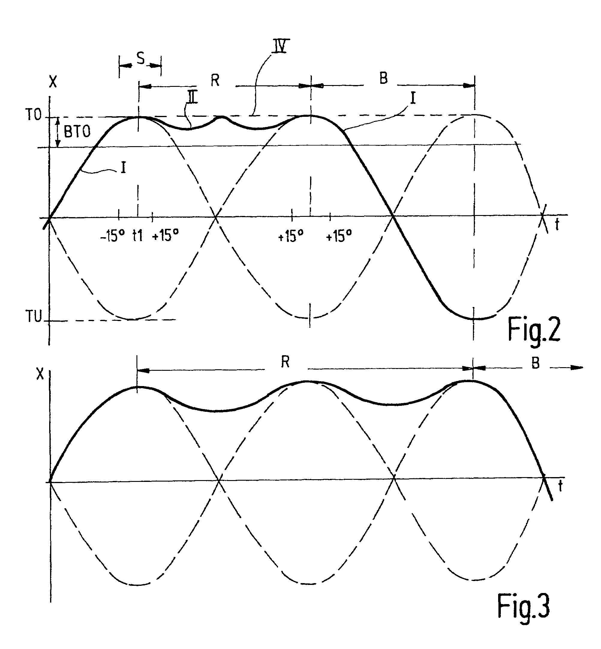
[0033]Turning now to FIG. 2, the curve I describes th...


PUM


Abstract

A new shaft drive provides for a switch-on and switch-off of individual heald shafts even at high working speeds. For this purpose switching pawls are provided which couple an eccentric with permanently revolving and / or back-and-forth oscillating disks. Measures for improving the controllability of such a clutch device are the control of the switching pawls by slot guides, associating bi-stabile biasing devices with the switching pawls and / or dividing the switching function into individual switching pawls (27a, 27b) which are associated individually with differently running disks (21, 22). Preferably, one of the two disks executes a continuous rotary motion, while the respective other disk performs only an oscillating motion which determines the heald shaft motion during the resting phases thereof.

Description

CROSS REFERENCE TO RELATED APPLICATION[0001]This application claims the priority of German Patent Application No. 10 2004 055 381.5, filed on Nov. 17, 2004, the subject matter of which, in its entirety, is incorporated herein by reference.BACKGROUND OF THE INVENTION[0002]This invention relates to a shaft drive for at least one heald shaft of a weaving machine.[0003]For shed building in weaving machines, as a rule, several heald shafts are provided, each having a plurality of mutually parallel-arranged healds. The warp yarns are passed through the yarn eyelets of the healds. For shed building, the heald shafts are moved very rapidly up and down. For this purpose shaft drives are provided which are designated as shaft machines or eccentric machines. Eccentric machines generate an upward and downward motion of the heald shafts from the rotary motion, making possible high weaving speeds. However, such eccentric machines are inflexible. The production of patterns or various textures is f...

Claims


Application Information

Patent Timeline
Patent Type & Authority Patents(United States)
IPC IPC(8): D03D51/46D03C9/06D03C15/00D03D51/02
CPCD03C1/00D03C1/14
Inventor BRUSKE, JOHANNESMUNSTER, BERNHARDFALLER, ARMIN
Owner GROZ BECKERT KG
Why Eureka
Try Eureka