Deep-drawing machine for producing deep-drawn objects, containers, packaging or similar and method for producing objects of this type

a technology of deep-drawing machine and thermoforming machine, which is applied in the direction of feeding apparatus, automatic control device, domestic objects, etc., can solve the problems of cost-effective and economic operation of the machine, and achieve the effect of simple machine structure arrangement and rapid and cost-effective mode of operation

Inactive Publication Date: 2006-06-01
G N PLASTICS COMPANY
View PDF6 Cites 0 Cited by
  • Summary
  • Abstract
  • Description
  • Claims
  • Application Information

AI Technical Summary

Benefits of technology

[0008] The present invention aims to provide a deep-drawing machine or thermoforming machine, and a method for producing deep-drawn articles, which allow for the production of the most diverse articles and, in particular, mass products from thermoformable plastic sheets or plates even of extreme heights, objects that can only be manufactured by pre-stretching processes or positive deep-drawing techniques and even such articles having U-edges. Moreover, the machine is to operate with extremely little waste and little energy input, and the number of processing stations is to be expandable in any desired manner.
[0009] To solve this object, the invention provides a thermoforming machine for the production of deep-drawn articles, containers, packages or the like, which is characterized in that processing stations are arranged or positioned along at least two, particularly parallelly extending, rows or lines. By the fixing means being separated and independent from one another, it is feasible to minimize the sheet scrap occurring on the edges of the fixing means and to operate in a cost-effective and economic as well as material-saving manner. Due to the fact that, in addition, the processing stations are arranged or positioned along at least two, particularly parallelly extending, rows or lines, the cycle time of the device can be remarkably reduced while, at the same time, achieving extreme energy savings and short cycle times. And by the fixing means being configured as tenter frames not fixedly connected with the machine, individual size adjustments of the fixing means to the sheet blanks to be processed are also feasible so as to allow the sheet blanks to be further minimized. By tentering the sheet blanks or plate blanks in tenter frames, it is feasible to minimize the scrap occurring on the edges of the fixing means and, hence, operate in a material-saving manner. Due to the fact that the tenter frames may, furthermore, be made of light metal or synthetic material and are firmly connected neither with the machine nor with one another, it is feasible to keep the conveying times of the tenter frames to the individual processing stations very short with little energy input, thus causing the machine to operate cost-effectively and economically with short cycle times.
[0010] By the fixing means being movable along slide bearings or guides made, in particular, of synthetic materials, the rapid, low-noise and energy-saving guidance of the fixing means along the parallelly extending lines or rows is feasible so as to achieve additional energy savings over known carrousel systems, where the whole systems must be moved in a disadvantageous manner. It is, furthermore, possible by the fixing means being movable along slide bearings or guides, to rapidly and readily exchange wear parts without involving long stop periods of the machine, thus providing an additional increase in the efficiency of the deep-drawing machine.

Problems solved by technology

Due to the fact that the tenter frames may, furthermore, be made of light metal or synthetic material and are firmly connected neither with the machine nor with one another, it is feasible to keep the conveying times of the tenter frames to the individual processing stations very short with little energy input, thus causing the machine to operate cost-effectively and economically with short cycle times.

Method used


Image

  • Deep-drawing machine for producing deep-drawn objects, containers, packaging or similar and method for producing objects of this type
  • Deep-drawing machine for producing deep-drawn objects, containers, packaging or similar and method for producing objects of this type
  • Deep-drawing machine for producing deep-drawn objects, containers, packaging or similar and method for producing objects of this type

Examples


Embodiment Construction

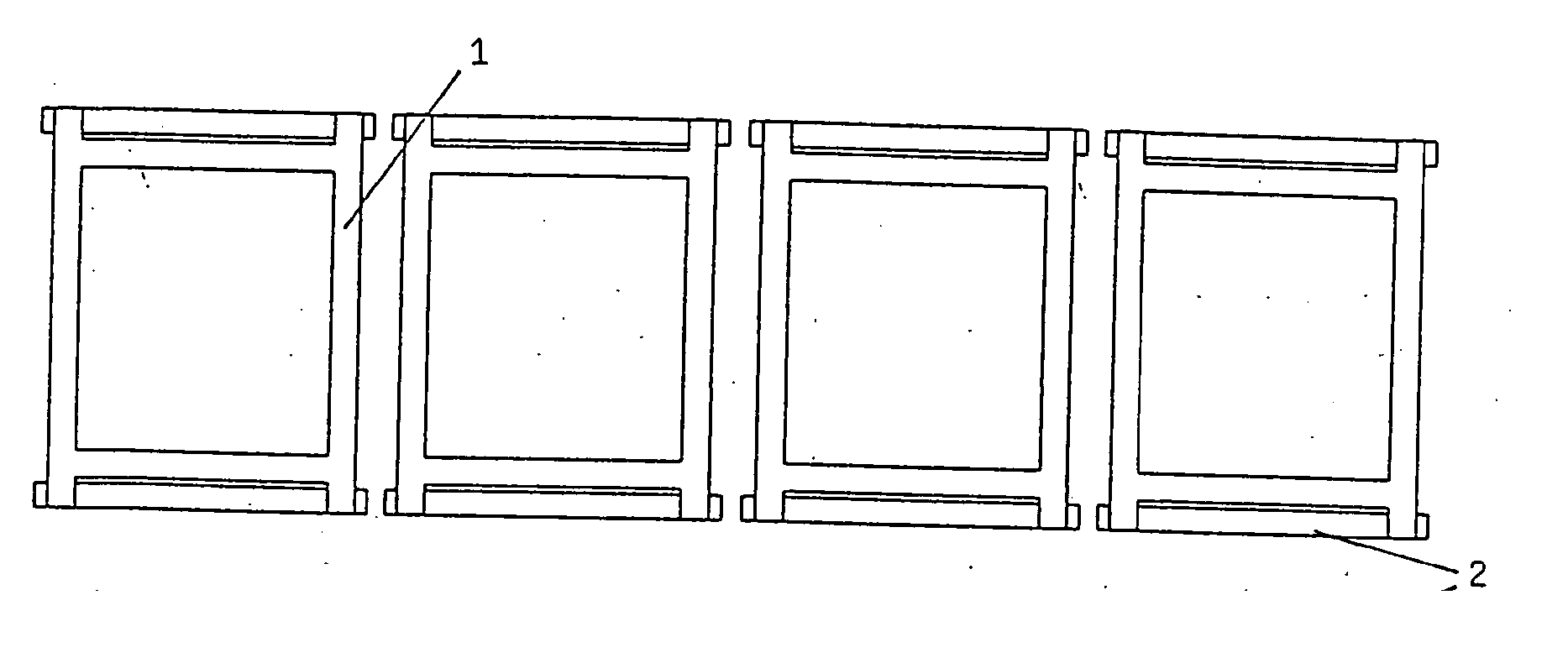
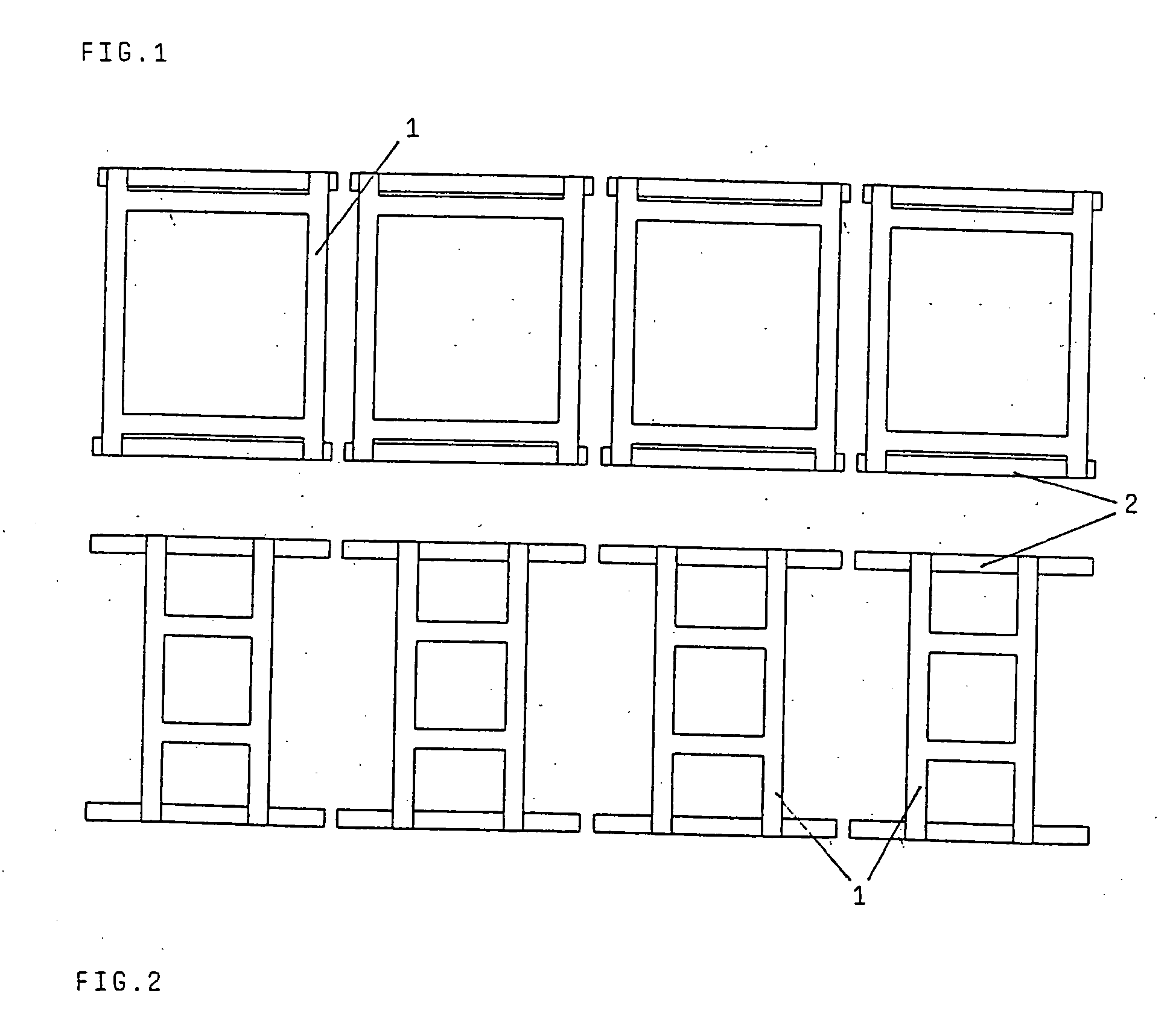
[0023]FIG. 1 depicts a thermoforming machine or deep-drawing machine comprising four large tenter frames 1 running on slide ledges 2. By such an arrangement of the tenter frames, the distance between the individual processing stations will always be the same both with large tenter frames 1 as in accordance with FIG. 1 and with small tenter frames as in accordance with FIG. 2, it being thereby feasible to attach the mechanisms of the individual processing stations not movably as in machines with chain conveyors, but fixedly so as to allow for a substantial reduction of the production costs of the machine.

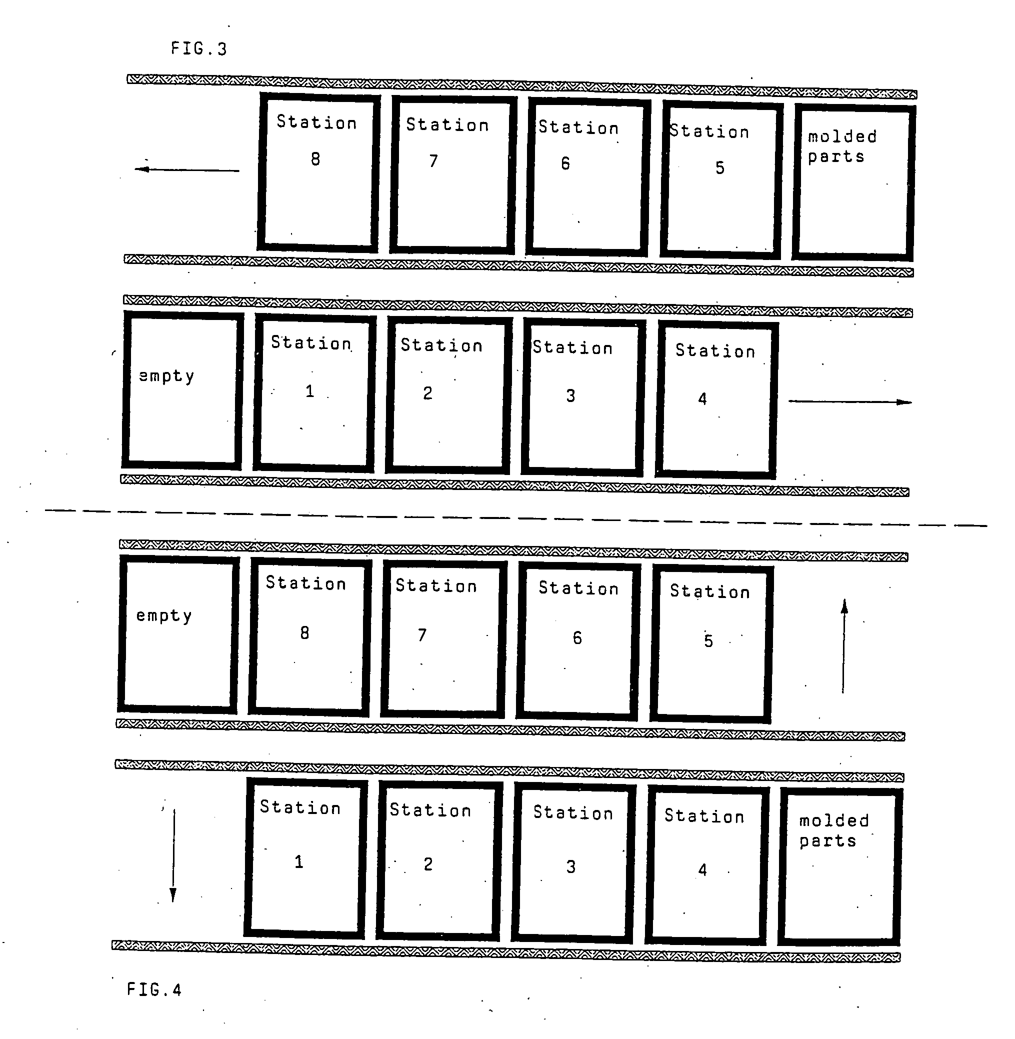
[0024] The example outlines a thermoforming machine according to FIGS. 3 to 12, which includes eight stations, yet this does not mean that the number of processing stations is limited to eight according to the invention. In FIG. 3, the eight stations are denoted by numbers as follows: Station 1 is the inserting station, where a sheet or plate blank is inserted into the tenter frame ...


PUM

PropertyMeasurementUnit
cycle timeaaaaaaaaaa
timeaaaaaaaaaa
half-timeaaaaaaaaaa

Abstract

The invention relates to a deep-drawing machine or thermoforming machine for producing diverse objects, containers, packaging or similar from thermoformable plastics. In said machine, plastic blanks are placed in retaining devices, in particular in holding presses (1) and the latter can be displaced in relation to the processing stations The retaining devices or holding presses (1) are separated from or independent of one another and the processing stations are situated or positioned along at least two rows or lines, which are in particular parallel.

Description

BACKGROUND OF THE INVENTION [0001] The present invention relates to a deep-drawing machine or thermoforming machine for the production of deep-drawn objects or articles, containers, packages or the like, from thermoformable plastic sheets or plates, wherein sheet or plate blanks are arranged in fixing means, particularly tenter frames, and movable relative to processing stations, said fixing means being separated and independent from one another. PRIOR ART [0002] Deep-drawing machine or thermoforming machines have been known in the art for quite some time and are used for the production of a plurality of articles or objects from thermally formable plastic sheets or plastic plates. Basically, three types of machines are to be distinguished in the deep-drawing technology. [0003] With the first known type of deep-drawing machines or thermoforming machines, sheet blanks or plate blanks are introduced into tenter frames which are fastened to a carrousel-like machine, thus running through...

Claims


Application Information

Patent Timeline
Patent Type & Authority Applications(United States)
IPC IPC(8): B23P21/00B23P19/00B29C51/18B29C51/26
CPCB29C51/18B29C51/261B29C51/262Y10T29/534B29L2031/3067Y10T29/53048Y10T29/53417B29C2793/009
Inventor NEMESKERI, KARL
Owner G N PLASTICS COMPANY
Why Eureka
Try Eureka