Segmented composite rotor

a composite rotor and axial geometry technology, applied in the direction of rotating magnets, magnetic circuit rotating parts, synchronous machines with stationary armatures, etc., can solve the problems of inefficient motor design, difficult axial geometry of rotor design and construction, and high speed design that is considered particularly challenging, so as to improve the cost effectiveness of the device, the effect of high efficiency and efficient construction

Inactive Publication Date: 2010-05-11
BERG & BERG ENTERPRISES
View PDF18 Cites 24 Cited by
  • Summary
  • Abstract
  • Description
  • Claims
  • Application Information

AI Technical Summary

Benefits of technology

[0021]In preferred embodiments, a rotor structure constructed in this manner has high strength and low weight, rendering it useful for electric machines, especially those operating at high rotational speeds. Such a configuration permits the expensive composite reinforcing material to be used efficiently, with fibers concentrated and preponderantly oriented in the direction requiring high strength, and with little if any waste of the reinforcing material.
[0025]In preferred embodiments, the foregoing composite rotor, and electric machines incorporating it, provide high efficiency and ability to operate at high rotational speeds. Such a machine is compact, lightweight, and efficiently constructed. Designs may incorporate very thin permanent magnet sections, improving the cost effectiveness of the device. Thinner magnets and elimination of the metallic support structure needed in previous rotors both reduce the rotor weight, minimizing its moment of inertia. In addition, a composite rotor markedly minimizes or eliminates deleterious circulating eddy currents, especially if the reinforcing fiber is non-conductive. The bonded composite reinforcement nevertheless provides the rotor with sufficient rigidity and high strength, as for high-speed operation.

Problems solved by technology

However, rotor design and construction are generally regarded as more difficult in the axial geometry.
High speed designs are considered particularly challenging as a result of the combined axial and radial forces encountered during operation.
High speed electric machines are almost always manufactured with low pole counts, lest the magnetic materials in electric machines operating at higher frequencies experience excessive core losses that contribute to inefficient motor design.
It is well known that losses resulting from changing a magnetic field at frequencies greater than about 400 Hz in conventional Si—Fe-based materials causes the material to heat, oftentimes to a point where the device cannot be cooled by any acceptable means.
However, further problems arise in electric machines from circulating eddy currents.
These problems are accentuated in devices operating at high frequencies and high speeds.
Circulating eddy currents bring a number of undesirable effects.
In some cases, they are high enough to cause significant heating in the rotor.
The heating, in turn, is likely to cause irreversible loss of magnetization of the rotor permanent magnets, thereby drastically reducing device output.
In extreme cases, the heating may even be severe enough to reduce the lifetime of the rotor magnets or destroy them.
A potentially even more serious problem arises from any current paths that traverse the shaft bearings.
Inevitably, shaft currents cause sparking and gradual erosion of bearing surfaces.
This in turn results in excess friction that can cause the bearings to overheat and even fail catastrophically.
This expedient may protect the bearing surfaces, but does not eliminate heating and its effects, not least the loss of energy efficiency.
Moreover, the brushes and slip rings themselves are expensive, require regular maintenance or replacement, and occupy valuable shaft space.

Method used


Image

  • Segmented composite rotor
  • Segmented composite rotor
  • Segmented composite rotor

Examples


Embodiment Construction

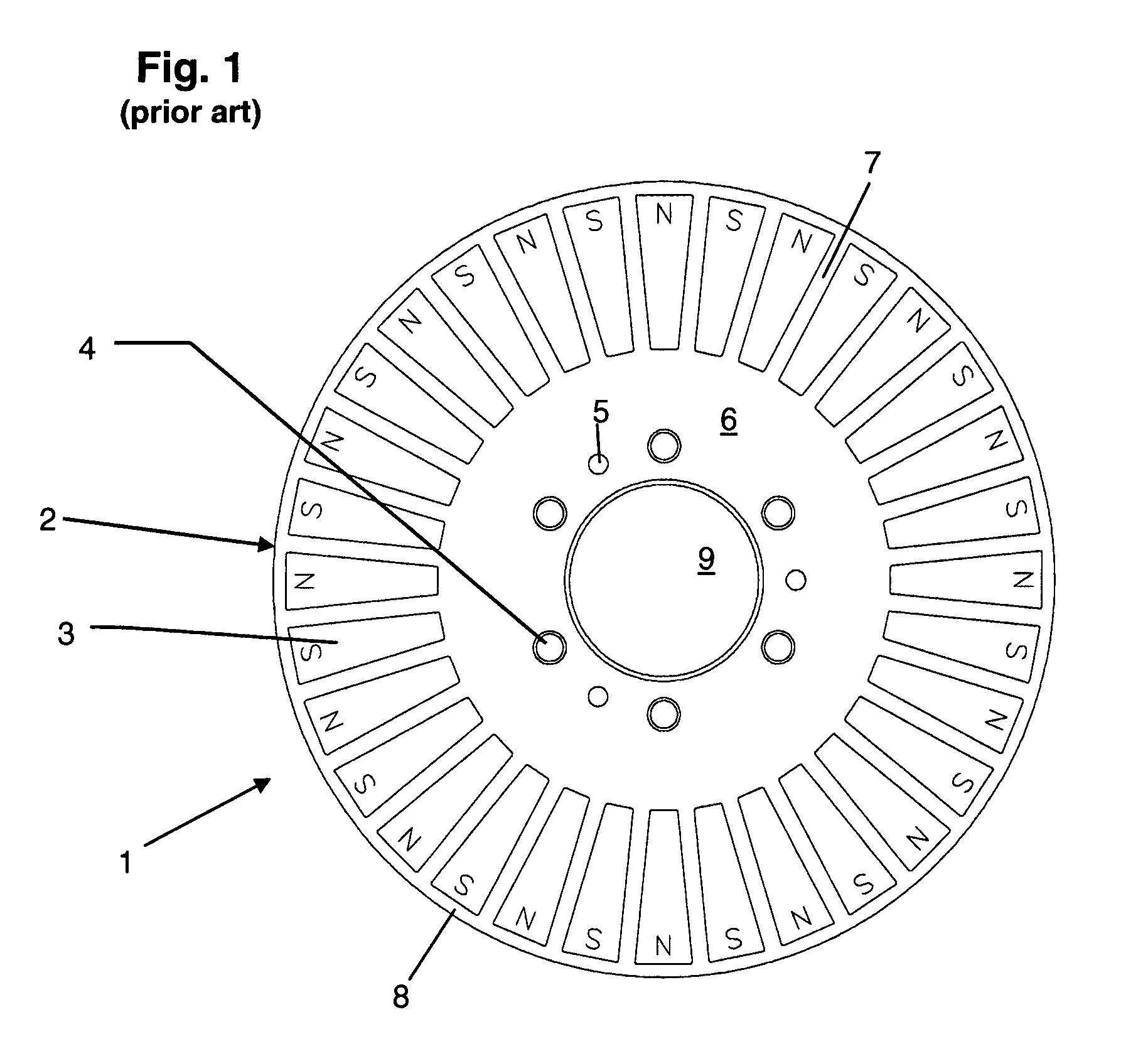
[0032]Referring to FIG. 1, there is depicted a permanent magnet rotor 1 used in a prior art, axial airgap, dynamoelectric machine. Rotor 1 is generally has the shape of a flat, low aspect ratio disk or plate. It comprises a plurality of permanent magnets 3 spaced around the circumference of support structure 2. The rotor is connected to a machine shaft in a conventional manner that may include a hub on either or both sides or other like structure (not shown) that engages support structure 2 and is attached to it using a plurality of fasteners, such as bolts or rivets, passed through mounting holes 4 symmetrically disposed on a bolt circle around a central aperture 9 through which the machine shaft passes. Alignment holes 5 are optionally provided to engage alignment pins in the hubs. Support structure 2 is typically fabricated from a non-magnetic metal by forming the required openings in an initially solid plate, e.g. by any conventional machining method. The openings include a requ...


PUM

PropertyMeasurementUnit
frequenciesaaaaaaaaaa
aspect ratioaaaaaaaaaa
densitiesaaaaaaaaaa

Abstract

A composite rotor for an axial airgap, permanent magnet dynamoelectric machine comprises a plurality of magnet subassemblies adhesively bonded together to form the rotor. Each magnet subassembly comprises a rotor permanent magnet and an optional spacer. A fibrous belt is wrapped around the periphery of each subassembly to provide high tensile strength at least along the radial sides of the subassembly. The belt is preferably infiltrated with an adhesive agent, such as an epoxy resin, that is used to bond the subassemblies. The rotor is thereby provided with high strength and low mass, making it suitable for use in a high-speed, high pole count electric machine.

Description

BACKGROUND OF THE INVENTION[0001]1. Field of the Invention[0002]The present invention relates to a segmented composite rotor; and more particularly, to a rotor for a permanent magnet, dynamoelectric machine, a method for fabricating such a rotor to provide it with improved strength and reliability for operating the machine at high rotational speeds, and a dynamoelectric machine incorporating such a rotor.[0003]2. Description of the Prior Art[0004]The electric motor and generator industry is continuously searching for ways to provide dynamoelectric, rotating machines with increased efficiencies and power and torque densities. As used herein, the term “motor” refers to all classes of motoring and generating machines which convert electrical energy to rotational motion and vice versa. Such machines include devices that may alternatively function as motors, generators, and regenerative motors. The term “regenerative motor” is used herein to refer to a device that may be operated as eith...

Claims


Application Information

Patent Timeline
Patent Type & Authority Patents(United States)
IPC IPC(8): H02K1/22
CPCH02K1/2793Y10T29/49012H02K29/03H02K21/24H02K15/03H02K1/2795
Inventor SENEFF, RICHARD LEXHIRZEL, ANDREW D.
Owner BERG & BERG ENTERPRISES
Why Eureka
Try Eureka