

Low power high-efficiency heating element
- Summary
- Abstract
- Description
- Claims
- Application Information
AI Technical Summary
Benefits of technology
Problems solved by technology
Method used
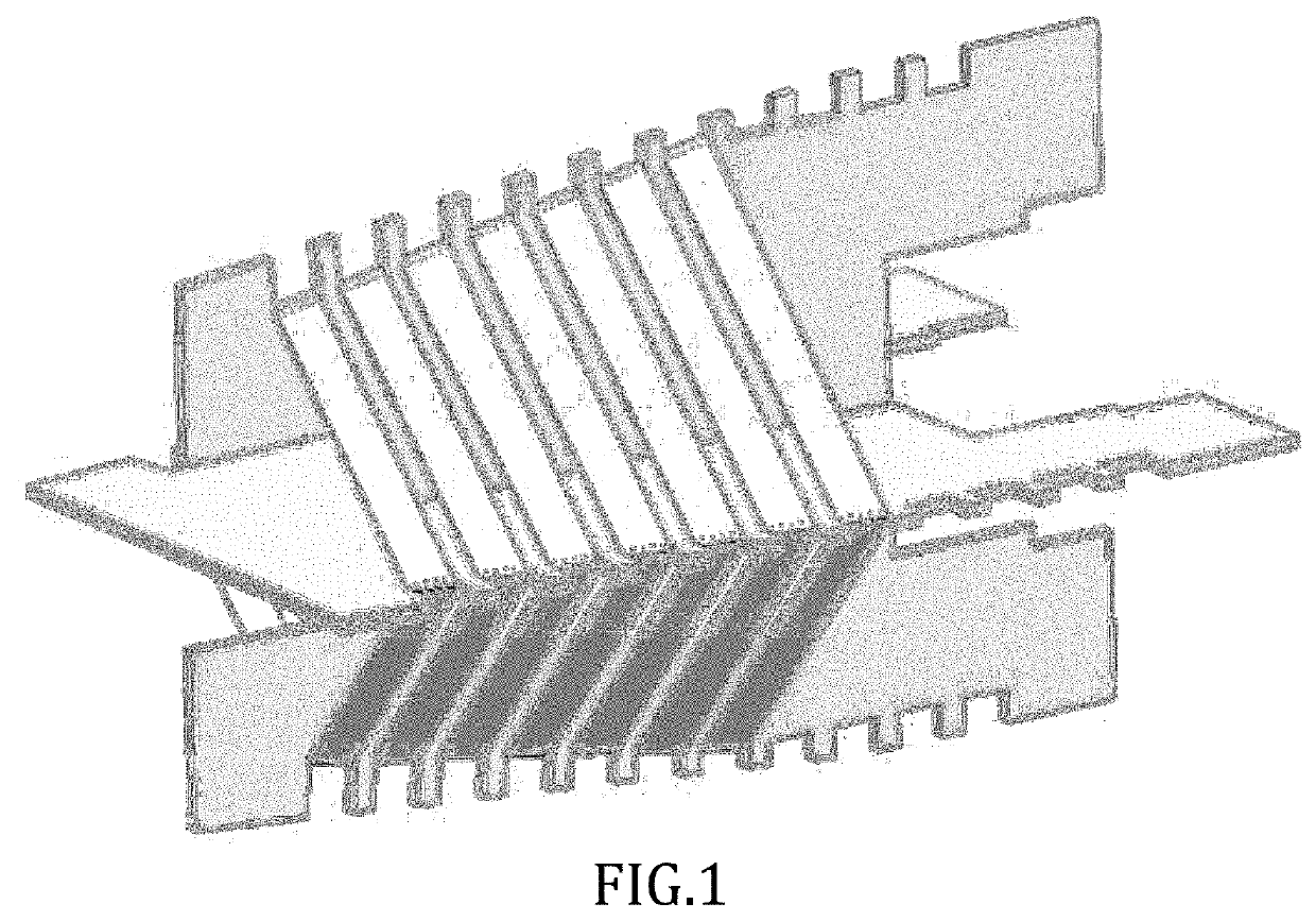
Image

Examples
example 1
on of Low Energy Heater Element
[0079]Element: Nickel-Chromium alloy and / or Iron Alloy
a. Coating: Chemical mixture of Graphite and Silica Carbide
b. Width: 4 mm
c. Thickness: 0.4 mm
d. Length: 240 mm
e. Total surface area: 2112 mm2
f. Volt DC: 12V
g. Current: 5 A
h. Resistance: 2Ω
i. Power: 55 W-60 W
j. Temperature@ 60 W: 270° C.
example 2
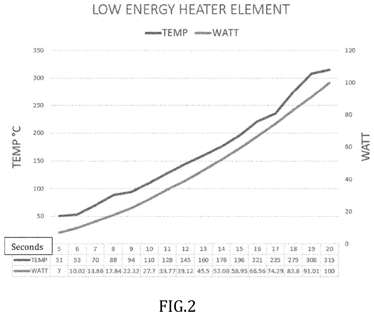
y Heater Element (Temp=Line Above; Watt=Line Below)
[0080]See FIG. 4 showing temperature and power vs time in seconds for low energy heater element.
Heater Strip Spec
[0081]Total surface area=7946 mm2[0082]Volume=1444.8 mm3[0083]Resistance=3.63Ω[0084]Strip length=903 mm[0085]Strip thickness=0.4 mm[0086]Strip width=4 mm[0087]Input voltage=5V to 20V
example 3
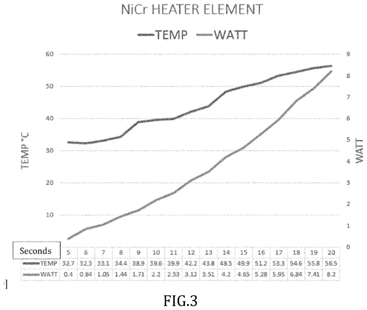
r Heater Element (Temp=Line Above; Watt=Line Below)
[0088]See FIG. 5 showing temperature and power vs time in seconds for NiCr heater element.
NiCr Heater Wire Spec
[0089]Total surface area=2393 mm2[0090]Volume=479 mm3[0091]Resistance=52.4Ω[0092]Strip length=3808 mm[0093]Strip diameter=0.4 mm[0094]Input voltage=5V to 20V
PUM
 Abstract
Description
Claims
Application Information