Tool and method for drilling, reaming, and cutting

Inactive Publication Date: 2005-08-25
CHRISMAN DAVID SCOTT
View PDF26 Cites 13 Cited by
  • Summary
  • Abstract
  • Description
  • Claims
  • Application Information

AI Technical Summary

Benefits of technology

[0008] Difficult formations and trips in and out of the well significantly reduce the rate of penetration (ROP) and introduce a dilemma for the driller regarding weight on bit (WOB) caused by the bit contacting the formation. To improve ROP, the driller can increase the WOB to drill hard formations faster, but the drill bit will wea

Problems solved by technology

There are massive costs associated with drilling below the earth's surface on land and the sea floor.
Capital costs tend to be one time costs of equipment including, but not limited to, the drilling platform, drilling rig, pump, drill pipe, trucks, tractors, and buildings.
As drilling takes place these costs can be compounded by difficult formations.
These difficult formations may include, but are not limited to, hard formations such as granite which wear out drill bits rapidly, sticky formations such as gumbo soil which can adhere to a drill bit and render it ineffective, and combinations of these and other formations.
These difficult formations frequently dictate that the driller trips out of the well, corrects the problem by replacing a worn or ineffective bit and then trips back into the well.
These round trips in and out of the well are time consuming and costly, often taking many hours, during which time no dril

Method used


Image

  • Tool and method for drilling, reaming, and cutting
  • Tool and method for drilling, reaming, and cutting
  • Tool and method for drilling, reaming, and cutting

Examples


Embodiment Construction

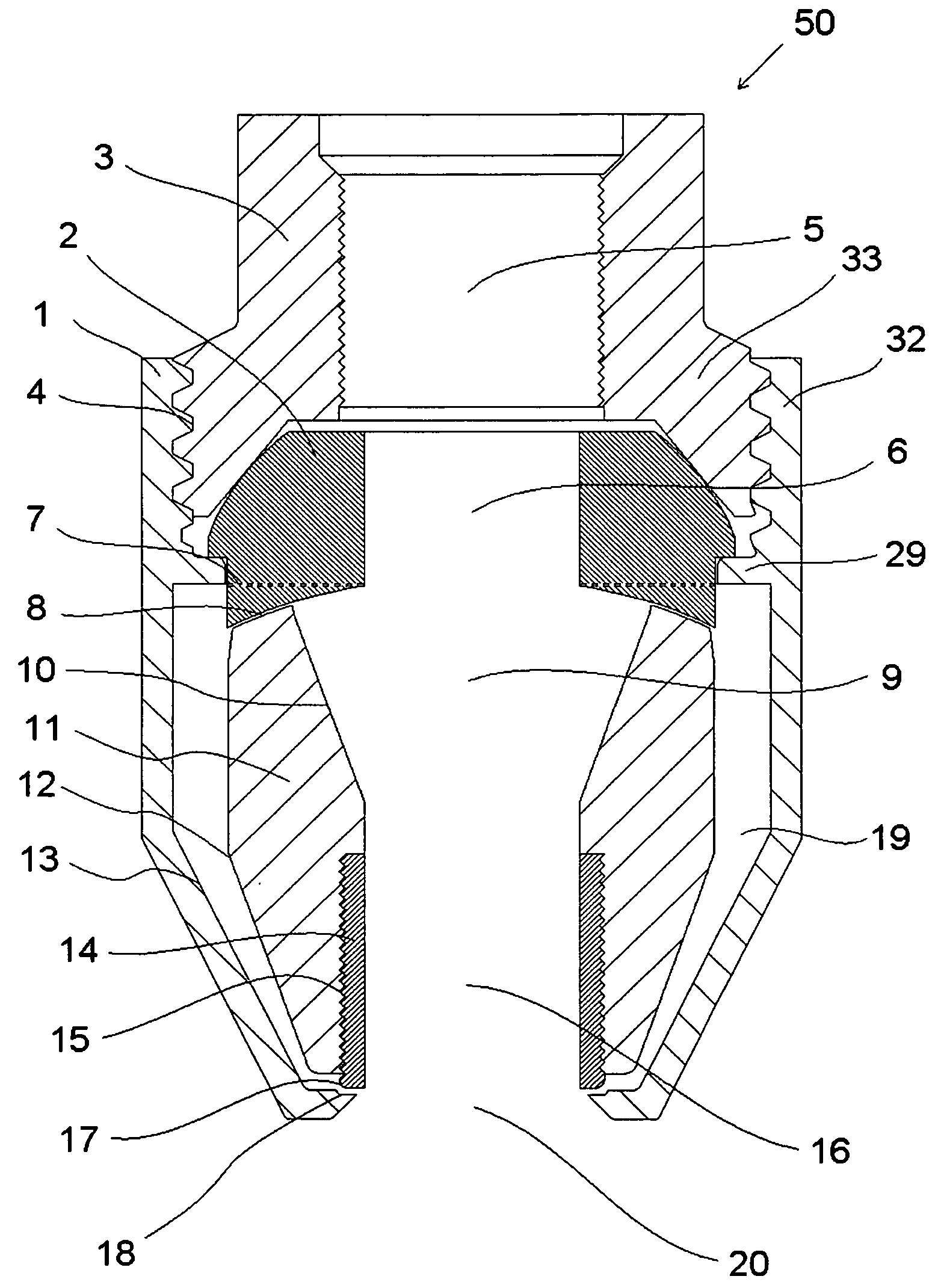
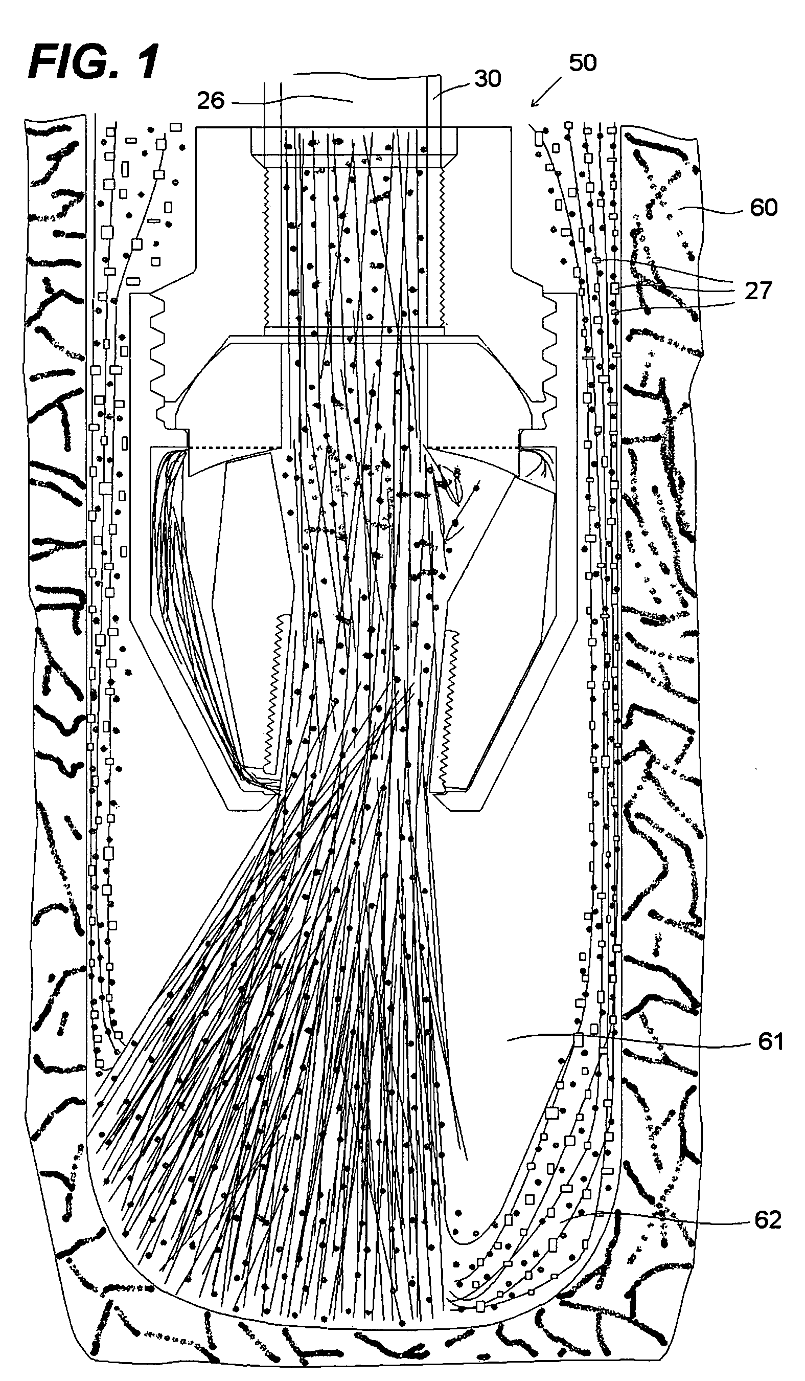
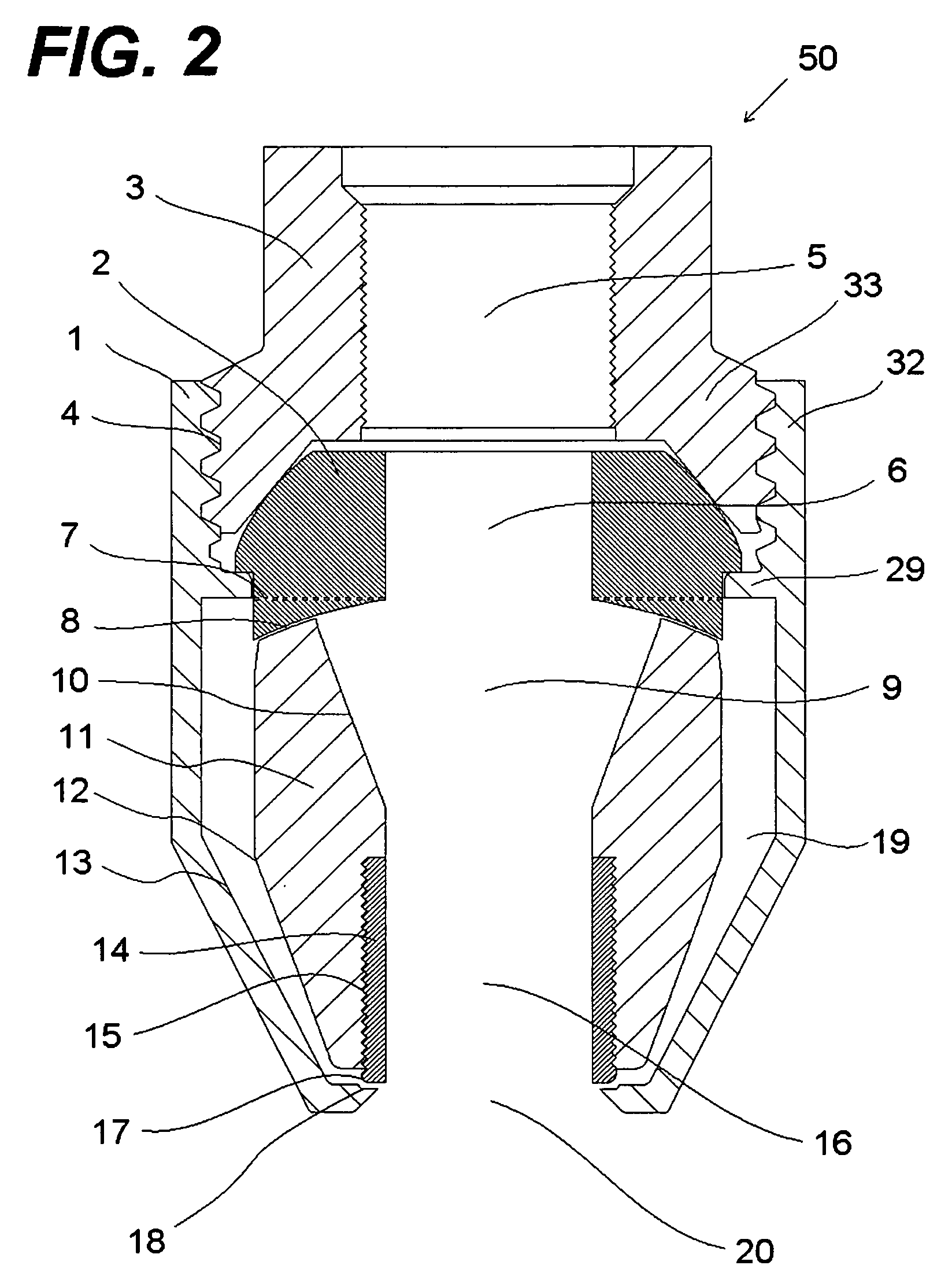
[0021]FIG. 1 shows one embodiment of an orbital tool 50 of the present invention coupled to a drill sting 30 near the bottom of a well bore 31 within a subterranean formation 60. The drill string 30 having a central passage 26 that allows fluid 25 to flow therein. As shown, the drill string 30 has a female threaded drill collar 3 that facilitates the connection of the orbital tool 50 to the drill string 30. Although FIG. 1 illustrates the orbital tool 50 being coupled to a drill string 30, the orbital tool 50 can be coupled to any type of conduit (e.g. tubing, hose, pipe) that allows fluid 25 to flow therein. Fluid 25, as used herein, refers to fluid in any state-gas, liquid, or solid, singularly or in combination. As will be explained in greater detail below, as the fluid 25 passes through the fluid pipeline 5 and into and out of the orbital tool 50, at least a portion of both the fluid 25 and, where applicable, any solids 24 suspended or mixed within the fluid 25 impinge the subte...


PUM


Abstract

An orbital tool apparatus and method of using the apparatus for boring, drilling, reaming, and cutting having a tool housing, a tool collar located within the housing, the tool housing having the ability to couple to a conduit structure, fluid orbiting jets within the tool collar, and a tool funnel located below the tool collar and within a lower portion of the tool housing. The orbital tool creating a bore in a surface, when fluid flowing into the orbital tool via a conduit is directed out of the orbital tool towards the structure, a portion of the fluid flowing within the orbital tool being diverted through the fluid orbiting jets causing the diverted fluid to impinge against the tool funnel, causing the tool funnel to oscillate creating a sweeping flow towards the surface.

Description

CROSS-REFERENCE TO RELATED APPLICATIONS [0001] This application claims priority from U.S. provisional application Ser. No. 60 / 541,800, filed Feb. 4, 2004.BACKGROUND OF THE INVENTION [0002] 1. Field of the Invention [0003] This invention relates to the field of drilling, reaming, and cutting tools and methods, in particular, to the drilling, reaming, and cutting of subterranean formations. [0004] 2. Background Summary [0005] There are massive costs associated with drilling below the earth's surface on land and the sea floor. These costs can broadly be grouped into two categories: capital costs and expenses. Capital costs tend to be one time costs of equipment including, but not limited to, the drilling platform, drilling rig, pump, drill pipe, trucks, tractors, and buildings. Expenses tend to be hourly costs or consumable material including, but not limited to, wages, food and lodging, electricity, water, fuel, equipment rentals, drill bits, drilling mud, geological and geophysical s...

Claims


Application Information

Patent Timeline
IPC IPC(8): E21B7/18E21B10/60E21B43/114
CPCE21B7/18
Inventor CHRISMAN, DAVID SCOTT
Owner CHRISMAN DAVID SCOTT
Why Eureka
Try Eureka