Electronic device with multiple buttons

a technology of electronic devices and buttons, applied in the field of electronic devices, can solve the problem that the button circuit design is not suitable for an electronic devi

Active Publication Date: 2005-08-25
BENQ CORP
View PDF2 Cites 10 Cited by
  • Summary
  • Abstract
  • Description
  • Claims
  • Application Information

AI Technical Summary

Benefits of technology

[0010] It is therefore an object of the invention to provide an electronic device with multiple buttons, which not only uses less GPIO pins of a microprocessor, but also equips the electronic device with multi-key function by means of an ADC I / O port only.

Problems solved by technology

Since each button uses a specific GPIO pin, and the microprocessor has a limited number of GPIO pins, such button circuit design is not suitable for an electronic device with a large number of buttons.

Method used


Image

  • Electronic device with multiple buttons
  • Electronic device with multiple buttons
  • Electronic device with multiple buttons

Examples


first embodiment

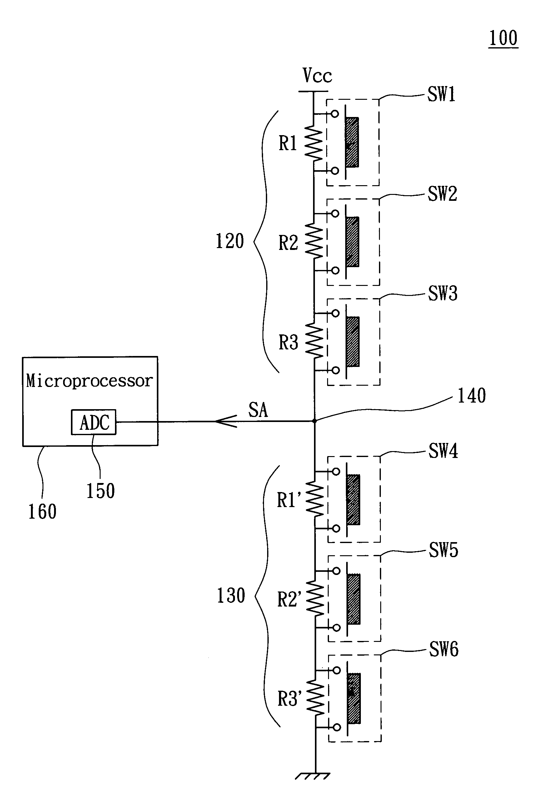
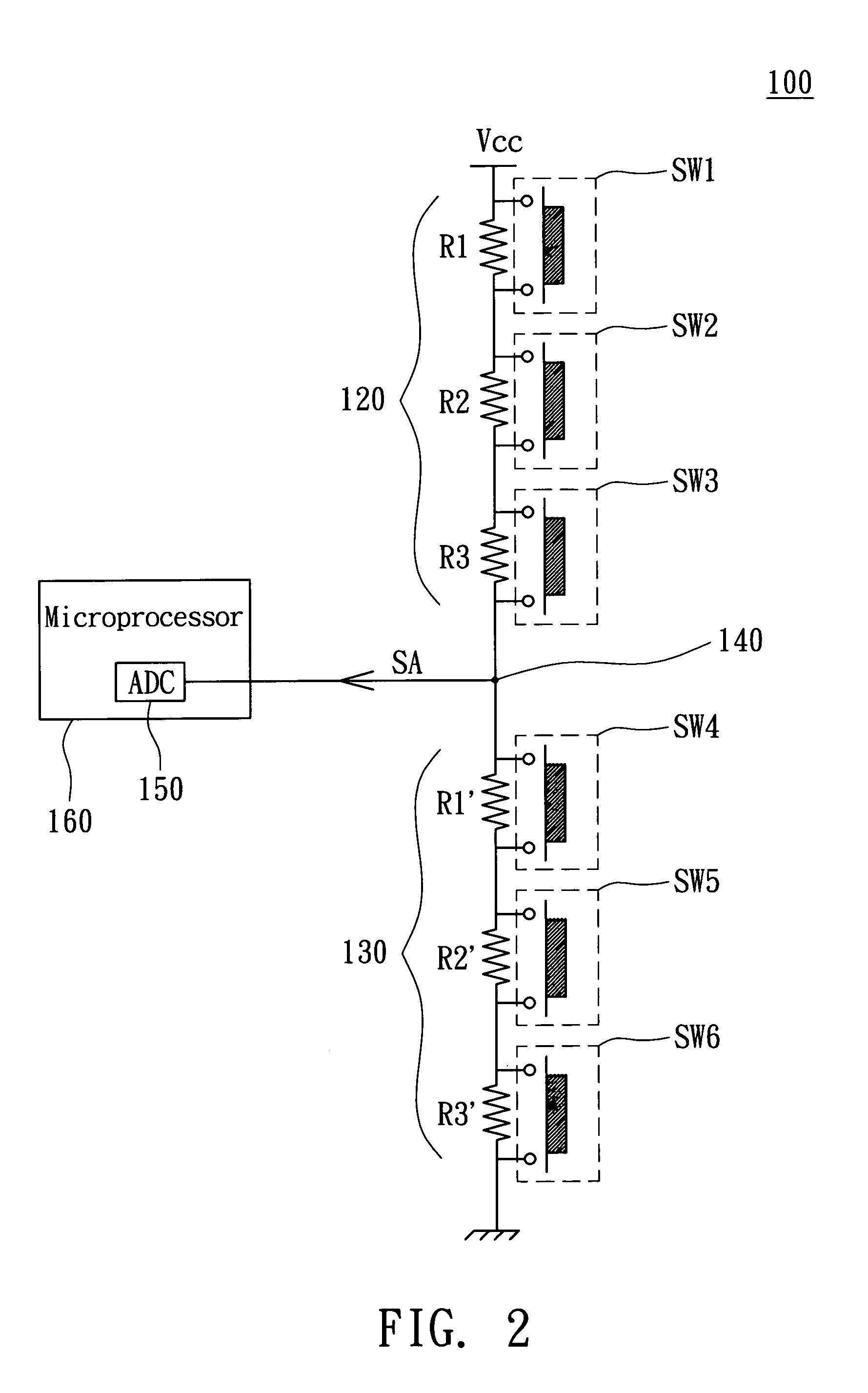
[0016] Referring to FIG. 2, a partial circuit diagram of an electronic device with multiple buttons according to a first embodiment of the invention is shown. Electronic device 100 includes a first resistor combination 120, a second resistor combination 130, 6 buttons SW1˜SW6, an output node 140, an analog-to-digital converter (ADC) 150 and a microprocessor 160.

[0017] The first resistor combination 120 has 3 serially connected resistors R1˜R3 with resistance R1˜R3 respectively. The second resistor combination 130 also has 3 serially connected resistors R1′, R2′ and R3′ with resistance R1′, R2′ and R3′ respectively. One end of the first resistor combination 120 and a high voltage Vcc are electrically connected, while another end of the first combination 120 is connected to an end of the second resistor combination 130. Another end of the second resistor combination 130 and a grounding voltage are electrically connected.

[0018] Besides, the buttons SW1˜SW6 are respectively connected ...

second embodiment

[0027] Referring to FIG. 3, a partial circuit diagram of an electronic device with multiple buttons according to a second embodiment of the invention is shown. The electronic device 200 includes a first resistor combination 220, a second resistor combination 230, three buttons SW1˜SW3, an output node 240, an analog-to-digital converter 250 and a microprocessor 260.

[0028] The first resistor combination 220 includes a resistor R1 with the resistance R1. The second resistor combination 230 includes two serially connected resistors R1′, R2′ with resistances R1′, R2′ respectively. An end of the first resistor combination 220 and a high voltage Vcc are electrically connected, while another end of the first resistor combination 220 is connected to an end of the second resistor combination 230. Another end of the second resistor combination 230 and a grounding voltage are electrically connected.

[0029] Besides, the buttons SW1˜SW3 are respectively connected in parallel with resistors R1, R...


PUM


Abstract

An electronic device with multiple buttons includes a first resistor combination, a second resistor combination, N buttons, and an output node. A first end of the first resistor combination is connected to a high voltage. A second end of the first resistor combination is connected to a third end of the second resistor combination. A fourth end of the second resistor combination is connected to a low voltage. The first resistor combination has p serially connected resistors, and the second resistor combination has q serially connected resistors. The sum of p and q equals M, a positive integer equal to or large than 3. Each button is connected in parallel with at least one resistor. The output node is deposited between the first and the second resistor combinations. The output node outputs an analog signal whose voltage corresponds to the states of the buttons.

Description

[0001] This application claims the benefit of Taiwan application Serial No. 093104160, filed Feb. 19, 2004, the subject matter of which is incorporated herein by reference. BACKGROUND OF THE INVENTION [0002] 1. Field of the Invention [0003] The invention relates in general to an electronic device, and more particularly to an electronic device with multiple buttons. [0004] 2. Description of the Related Art [0005] In a conventional electronic device, a common design of button circuit is to have buttons directly connected to pins of the microprocessor's general purpose input output (GPIO) for determining the state of buttons by the microprocessor directly. [0006] Although such a button circuit design has the advantages of being direct and simple, a large number of GPIO pins will be required when more buttons are needed. Since each button uses a specific GPIO pin, and the microprocessor has a limited number of GPIO pins, such button circuit design is not suitable for an electronic devic...

Claims


Application Information

Patent Timeline
Patent Type & Authority Applications(United States)
IPC IPC(8): H03M1/12H03M11/24
CPCH03M11/24
Inventor CHU, YAO-WEN
Owner BENQ CORP
Why Eureka
Try Eureka