
Connector module

a technology of connecting modules and connectors, applied in the direction of coupling devices, two-part coupling devices, electrical equipment, etc., can solve the problems of reducing the appearance dimension, small number of computers and concentrated computers cannot provide enough information and data for business use, etc., to achieve the effect of enhancing the conjunction strength therebetween and reducing the occupation area on the circuit board

Inactive Publication Date: 2005-08-25
DELTA ELECTRONICS INC
View PDF13 Cites 16 Cited by
  • Summary
  • Abstract
  • Description
  • Claims
  • Application Information

AI Technical Summary

Benefits of technology

[0007] It is an objective of the present invention to provide a connector module to integrate a control integrated circuit, connectors, and transformers so as to reduce the appearance dimension of the electrical equipment with the connector module.
[0008] It is another objective of the present invention to provide an RJ-45 connector module to integrate a control integrated circuit, a connector, and a transformer into the module shell and utilize the pins of the control integrated circuit to couple to a circuit board so as to reduce an occupation area thereof on the circuit board.
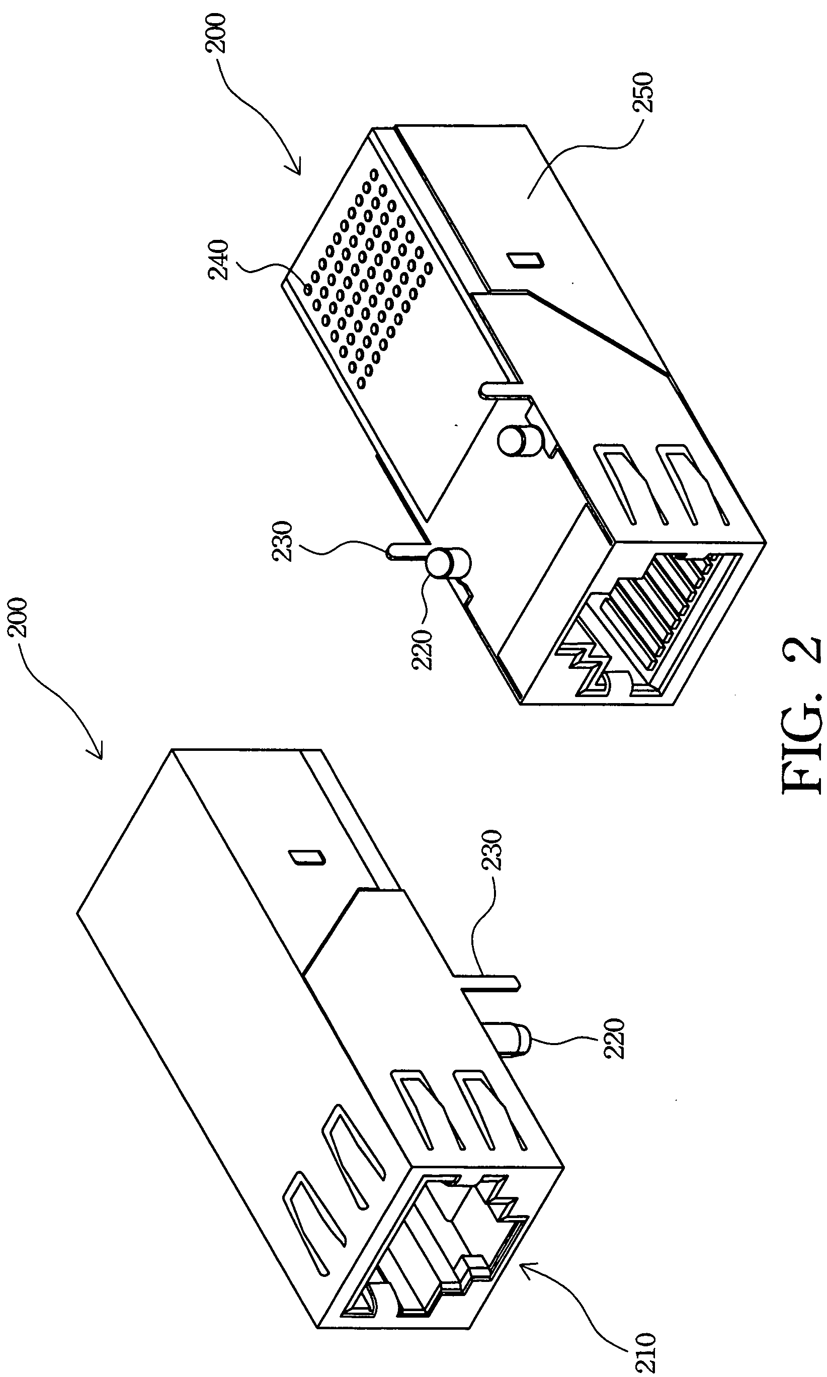
[0012] The connector module further has a positioner and a fixing member coupling to a bottom surface of the shell to couple accurately the connector module to the circuit board and to enhance a conjunction strength therebetween.
[0013] The connector module more preferably applies to RJ-45 connector to couple an electrical device to the network. Because the control IC and the transformer are integrated in the shell of the connector module, the connector module according to the present invention can utilize the pins of the control IC to couple to the circuit board so that the occupation area on the circuit board can therefore be effectively reduced. Accordingly, the appearance dimensions of the electrical equipment with the connector module can be therefore shrunk.

Problems solved by technology

Currently, only a small quantity of computers and concentrated computers cannot provide enough information and data for business utilization.
Hence, the connectors, transformers, and control integrated circuits have to occupy a predetermined area on the circuit board and become a bottleneck for reductions in the appearance dimensions of the electrical device.

Method used


Image

  • Connector module
  • Connector module
  • Connector module

Examples


Embodiment Construction

[0020] The following description is of the best presently contemplated mode of carrying out the present invention. This description is not to be taken in a limiting sense but is made merely for the purpose of describing the general principles of the invention. The scope of the invention should be determined by referencing the appended claims.

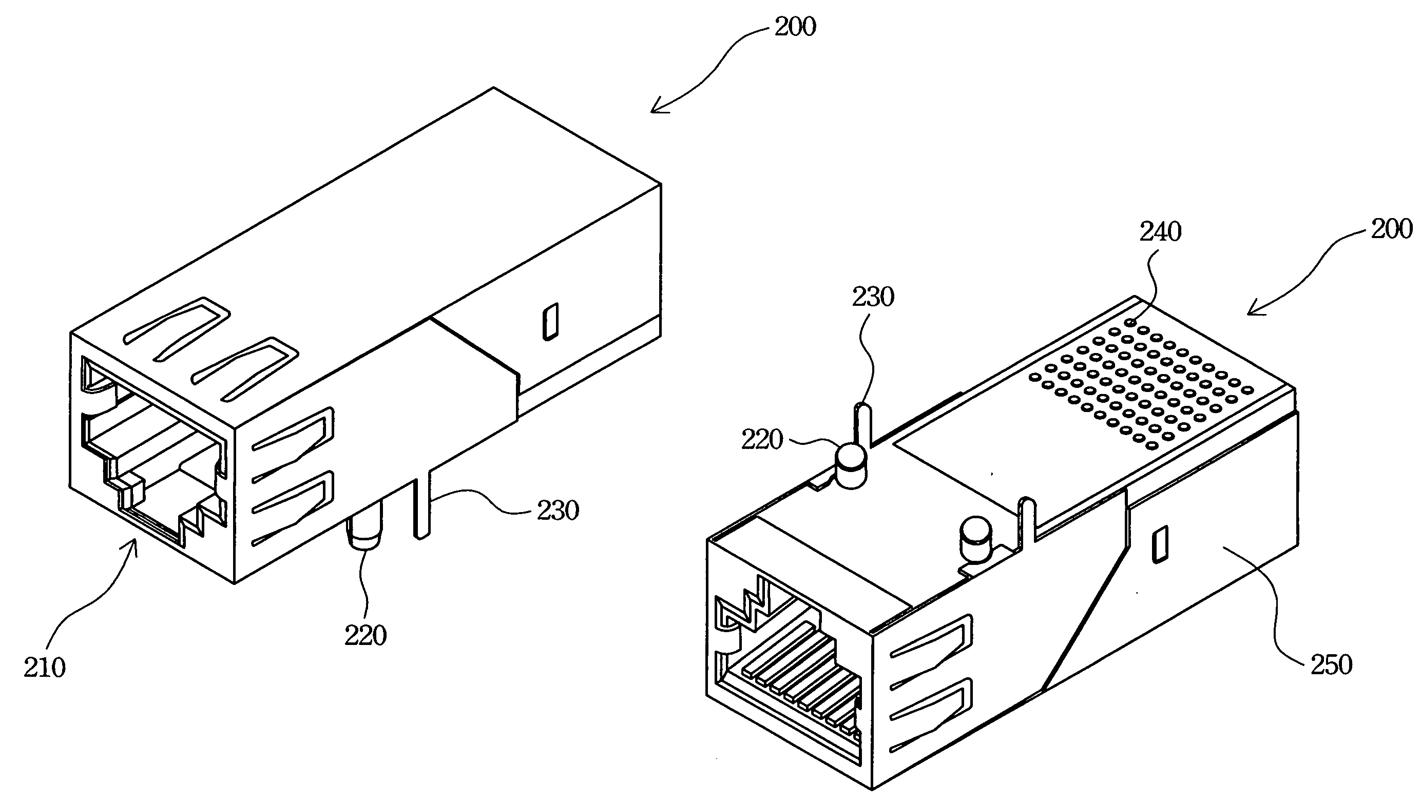
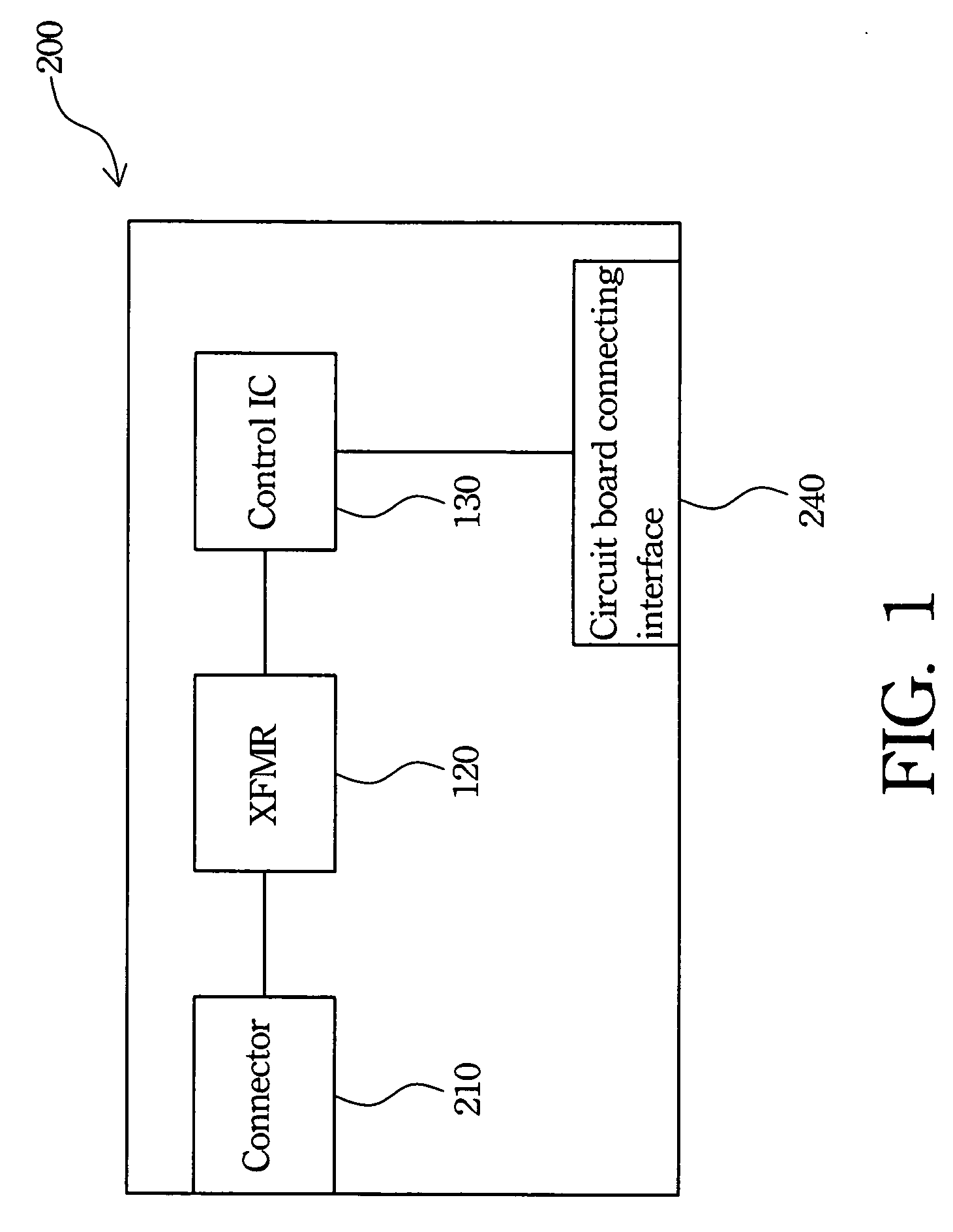
[0021]FIG. 1 is a block diagram of a connector module according to the present invention. The connector module 200 has a connector 210, a transformer 120, an integrated circuit (IC) 130, and a circuit board connecting interface 240. The connector 210 is coupled to a corresponding connector for transmitting signals. The transformer 120 transmits the signals, increases an insulation voltage between the network and the connector module 200, and further reduces an error rate of the transmitting signals. The control IC 130 provides functions to control and connect the connector module 200 to the network.

[0022]FIG. 2 is a schematic view of a first p...


PUM


Abstract

A connector module is described. The connector module efficiently reduces an occupation area of a connector and control circuits thereof on a circuit board and provides various circuit board connecting interfaces packaged by various package processes. The connector module has a shell, a connector, a control integrated circuit, and a circuit board connecting interface. The connector and the control integrated circuit are configured in the shell. The control integrated circuit controls signal transmissions for the connector module. The connector module further has a transformer configured in the shell.

Description

RELATED APPLICATIONS [0001] The present application is based on, and claims priority from, Taiwan Application Serial Number 93104661, filed on Feb. 24, 2004, the disclosure of which is hereby incorporated by reference herein in its entirety. FIELD OF THE INVENTION [0002] The present invention relates to a connector module, and more particularly, to a connector module with a transformer and an integrated circuit therein. BACKGROUND OF THE INVENTION [0003] Due to highly developed information technology, electrical and information products are more popular and convenient for users. Computer systems and peripherals thereof progress greatly, day by day, and people can search for information and provide services with networks. Via networks, people enjoy a comfortable and fast information search environment. [0004] The wide proliferation of personal computers and networks allows people to utilize networks to search for and provide information. Currently, only a small quantity of computers ...

Claims


Application Information

Patent Timeline
Patent Type & Authority Applications(United States)
IPC IPC(8): H01R13/66H01R24/00
CPCH01R13/6633H01R12/716H01R13/6658
Inventor HSU, HAN-CHENGCHEN, CHIH-TSEKAO, CHING-MAN
Owner DELTA ELECTRONICS INC
Learn More