Limited slip differential device

a differential device and limited technology, applied in the direction of magnets, magnetic bodies, gearings, etc., can solve the problem that the differential device keeps the slip-limit state, and achieve the effect of limiting the differential function of the differential gear

Active Publication Date: 2005-08-25
GKN DRIVELINE TORQUE TECHNOLOGY KK +1
View PDF8 Cites 43 Cited by
  • Summary
  • Abstract
  • Description
  • Claims
  • Application Information

AI Technical Summary

Benefits of technology

[0007] According to a first aspect of the present invention there is provided a limited slip differential device comprising: differential gears to obtain a differential function; a clutch to limit the differential function of the differential gears; a electromagnetic solenoid that has a plunger moving forward to engage said clutch in a differential limit state and moving backward to disengage the clutch in a differential limitless state, and a coil applying electromagnetic force to the plunger when the coil is ene

Problems solved by technology

The above known conventional limited slip differential device, however, encounters a problem that the differential device keeps the slip-l

Method used


Image

  • Limited slip differential device
  • Limited slip differential device
  • Limited slip differential device

Examples


first embodiment

[0031]FIGS. 3A and 3B show a differential limit mechanism in a differential unlock state and in a differential lock state, respectively, when the differential limit mechanism is constructed to have a plunger without a cut-off portion, for the sake of comparison with the differential limit mechanism 8 with the cut-off portions of the

[0032] The differential limit mechanism 8′ includes a yoke 81′, a coil 82′ disposed inside the yoke 81′, and a plunger 831′. The plunger 831′ has an outer ring part 831′ and an inner ring part 832′ as well as those of the first embodiment, except that they are not cut-off at their front and rear ends. In the differential unlock state, the coil 82′ is de-energized, and the plunger 83′ is pressed back by a return spring, not shown, to contact with a rear inner wall portion 81c′ of the yoke 82′ and disengage a dog clutch as shown in FIG. 3A. In the differential lock state, the coil 82′ is energized, and the plunger moves forward to push a piton plate, not sh...

second embodiment

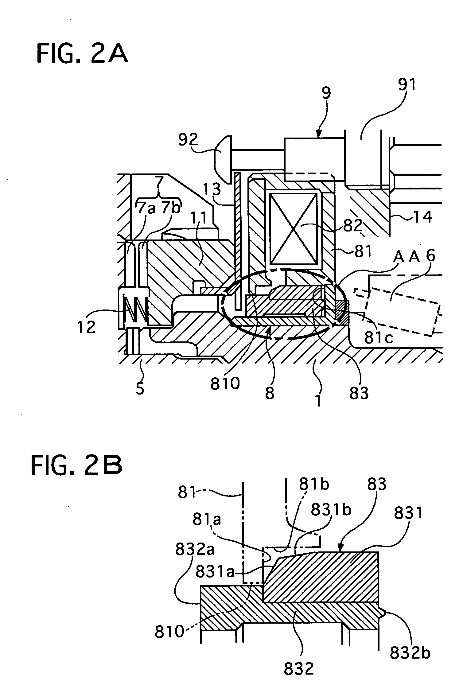
[0045] Next, a limited differential device of a second embodiment will be described with reference to the accompanying drawing of FIG. 4.

[0046] This differential device has a structure equipped with differential gears, a dog clutch, and a linear electromagnetic solenoid, which are similar to that of the first embodiment except configurations of a plunger and a yoke of a linear electromagnetic solenoid.

[0047] As shown in FIG. 4, a plunger 83 includes an outer ring part 831 and an inner ring part 832, which are joined with each other by press fit or the like. The outer ring part 831 has not a first and outer tapered portion such as those of the first embodiment, while a yoke 81 is formed at its center portion with a hole 810 surrounded by an inner stepped portion having an inner tapered surface 81d, an inner radial surface 81a, and an inner cylindrical surface 81b by cutting off an inner portion of the yoke 81. The inner tapered surface 81d is kept away from the outer ring part 831 w...

third embodiment

[0052] Next, a limited differential device of a third embodiment will be described with reference to the accompanying drawing of FIG. 5.

[0053] This differential device has a structure equipped with differential gears, a dog clutch, and a linear electromagnetic solenoid, which are similar to that of the first embodiment except configurations of a plunger and a yoke of a linear electromagnetic solenoid.

[0054] As shown in FIG. 5, a plunger 83 includes an outer ring part 831 and an inner ring part 832, which are joined with each other by press fit or the like. The outer ring part 831 has not a first and outer tapered portion such as those of the first embodiment, while a yoke 81 is formed at its center portion with a hole 810 surrounded by an inner stepped portion having an inner circular projecting portion 81e, an inner radial surface 81a, and an inner cylindrical surface 81b by cutting off an inner portion of the yoke 81. The inner circular projecting portion 81e contacts with an out...


PUM


Abstract

A limited slip differential device has differential gears, a clutch to limit the differential function of the differential gears, and a electromagnetic solenoid including a plunger and a coil. The plunger is set to move forward to engage the clutch by electromagnetic force of the coil in a differential limit state and move backward by a return spring to disengage said clutch in a differential limitless state. The plunger contacts with a contacting member in at least one state of the differential limit state and the differential limitless state, and their contact area is set smaller than a facing area between them in at least the one state.

Description

BACKGROUND OF THE INVENTION [0001] 1. Field of the Invention [0002] The present invention relates to a limited slip differential device that is capable of limiting its differential function by using an electromagnetic solenoid. [0003] 2. Description of the Related Art [0004] A limited slip differential device of this kind is disclosed in Japanese utility model laying-open publication No. (Hei) 05-29833. This differential device has differential gears consisting of a planetary gear set, a differential limit mechanism to limit differential function of the differential gears, and a housing containing the differential gears and the limit slip differential mechanism. The differential limit mechanism includes a multi-plate clutch and an electromagnetic clutch mechanism having a magnet plate, an electromagnetic solenoid to attract the magnet plate, and a clutch disposed between the magnet plate and the electromagnet solenoid. In this differential device, the solenoid controls a slip-limit ...

Claims


Application Information

Patent Timeline
IPC IPC(8): F16H48/24F16D27/10F16D27/118F16H48/08F16H48/295F16H48/30F16H48/34F16H48/38
CPCF16H48/08F16H48/24F16H48/30F16H2048/346F16H48/40F16H2048/204F16H48/34
Inventor HARUKI, YUYA
Owner GKN DRIVELINE TORQUE TECHNOLOGY KK
Why Eureka
Try Eureka