
Object defect depth measuring method with defect size being considered

A technology of defect depth and defect size, which is applied in the field of non-destructive testing, can solve problems such as defect size influence and error, and achieve the effect of improving measurement accuracy

Active Publication Date: 2018-05-25
CAPITAL NORMAL UNIVERSITY +2
View PDF4 Cites 9 Cited by
  • Summary
  • Abstract
  • Description
  • Claims
  • Application Information

AI Technical Summary

Problems solved by technology

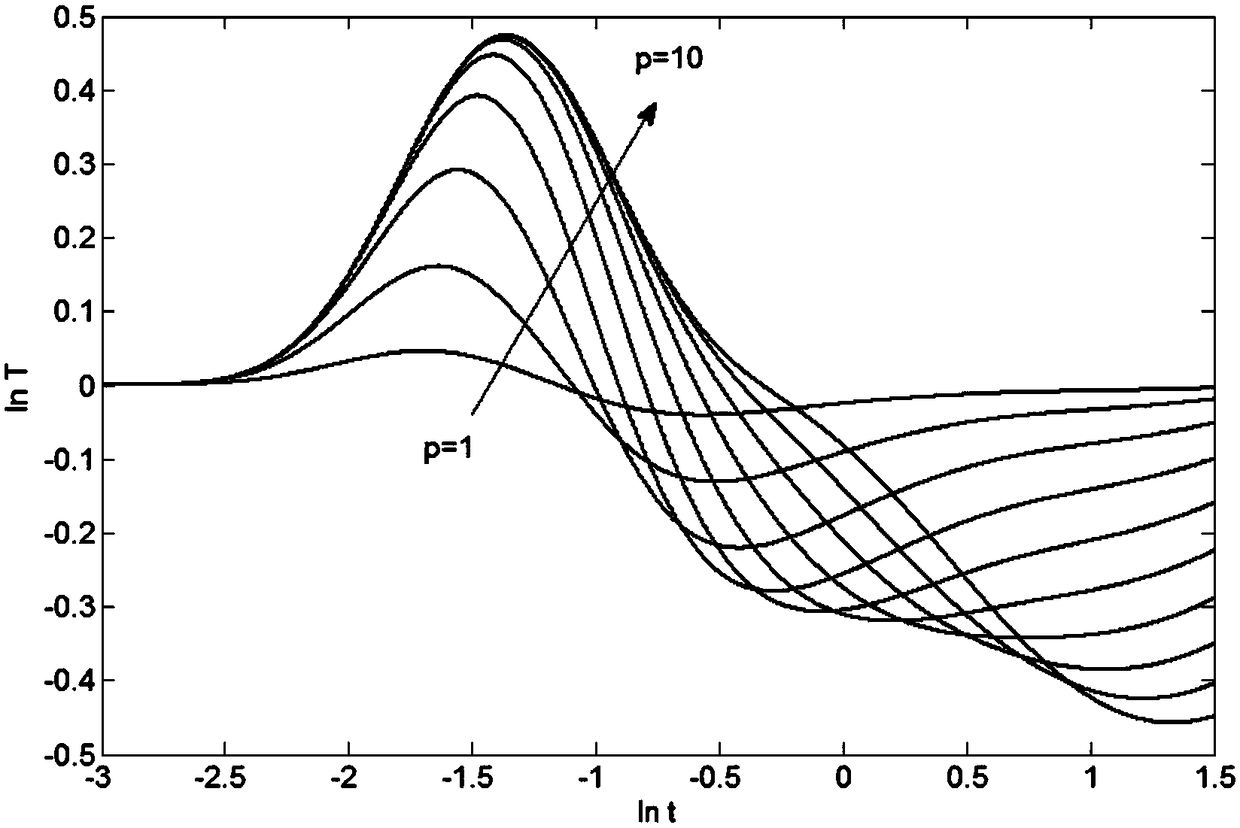
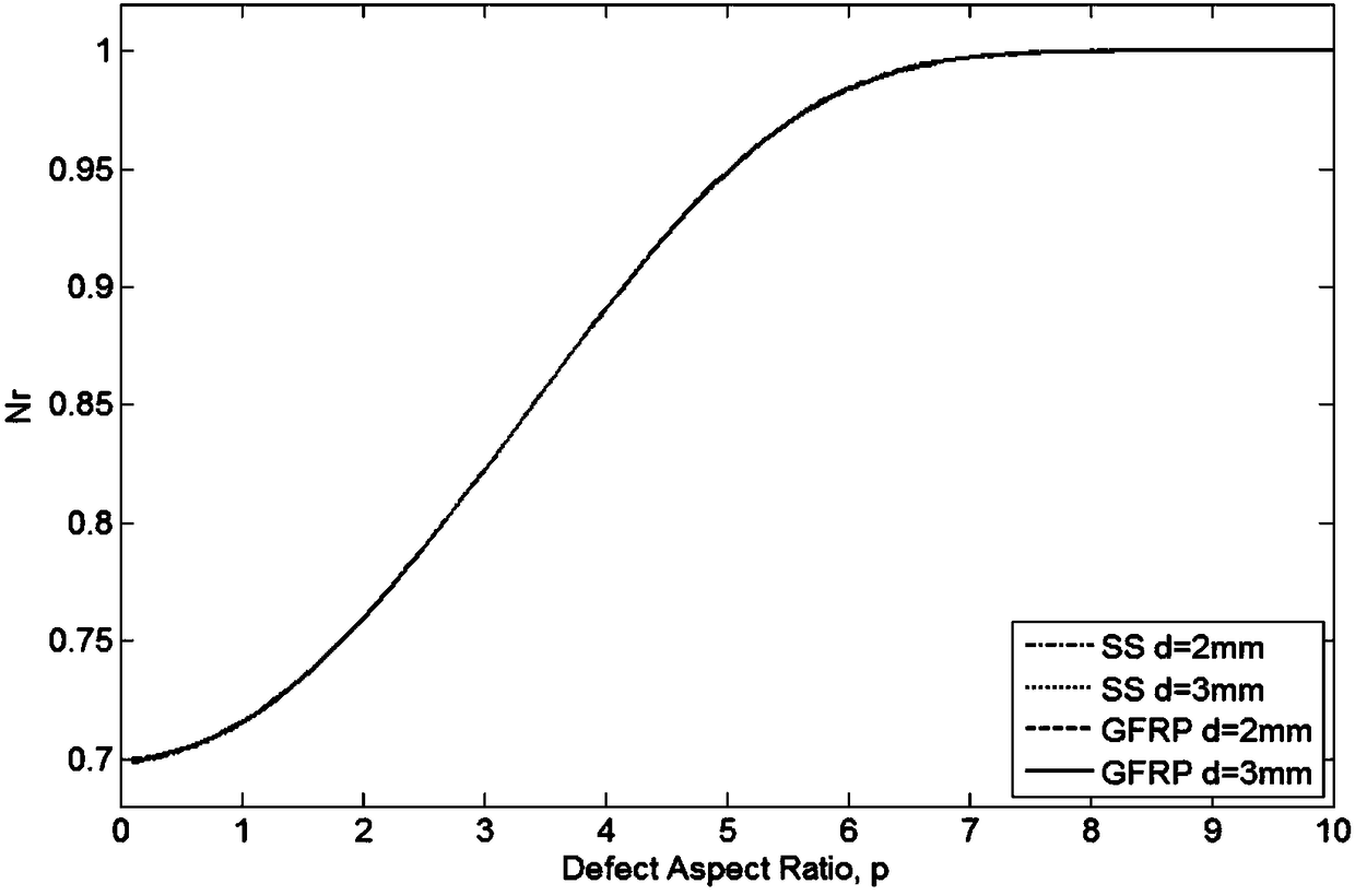
[0011] However, through a large number of experiments, it is found that the peak time of the currently applied second-order logarithmic differential peak method is affected by the defect size in the case of finite defect size
Therefore, if the peak time is obtained through the experimental data, and the defect depth is directly calculated by formula (3), it will bring a certain error

Method used


Image

  • Object defect depth measuring method with defect size being considered
  • Object defect depth measuring method with defect size being considered
  • Object defect depth measuring method with defect size being considered

Examples


Embodiment Construction

[0043] The following will clearly and completely describe the technical solutions in the embodiments of the present invention with reference to the accompanying drawings in the embodiments of the present invention. Obviously, the described embodiments are only some, not all, embodiments of the present invention. Based on the embodiments of the present invention, all other embodiments obtained by persons of ordinary skill in the art without making creative efforts belong to the protection scope of the present invention.

[0044] The theoretical basis of the present invention is to introduce a defect size factor on the basis of formula (2). Assume that the defect is a flat-bottomed hole defect with a diameter of D and a depth of L. Due to its larger thickness, the normal area cools faster than the defect area, that is, the temperature of the defect area is higher. Due to the influence of three-dimensional thermal diffusion, thermal diffusion from the center of the high-temperat...


PUM


Abstract

The invention discloses an object defect depth measuring method with the defect size being considered, which comprises the steps of S1, heating a measured object by pulse heating equipment, and obtaining thermographic sequence data of the surface of the measured object by an infrared thermal imaging device; S2, solving a second-order differential function of the logarithmic temperature-logarithmic time of the thermographic sequence data in allusion to the obtained thermographic sequence data, and extracting a corresponding time of peak tLPSD in the second-order differential function; S3, acquiring the defect diameter D of the measured object by using a full width at half maximum algorithm in allusion to the obtained thermographic sequence data; and S4, calculating the defect depth of themeasured object by using the correction method provided by the invention. According to the invention, the defect depth is measured on the condition that the defect size is considered, so that errors in the existing measurement technologies can be effectively reduced.

Description

technical field [0001] The invention relates to the technical field of non-destructive flaw detection, in particular to an infrared thermal wave technology and a method for measuring the thickness of a tested piece or the depth of a defect by using the logarithmic second-order differential peak time in consideration of the size of the defect. Background technique [0002] Pulse infrared thermal wave non-destructive testing technology is a non-destructive testing technology developed after the 1990s. This method is based on thermal wave theory, by actively applying pulsed thermal excitation to the object to be detected, and using an infrared thermal imager to continuously observe and record the temperature field changes on the surface of the object, and through modern computer technology and image information processing technology for time series Detection, acquisition, data processing and analysis of thermal wave signals to achieve quantitative diagnosis of internal defects ...

Claims


Application Information

Patent Timeline
IPC IPC(8): G01B15/00
CPCG01B15/00
Inventor 李晓丽曾智陶宁冯立春王迅沈京玲张存林
Owner CAPITAL NORMAL UNIVERSITY
Learn More