Electric drive system

a technology of electric drive and drive shaft, which is applied in the direction of electric propulsion mounting, transportation and packaging, gearing, etc., can solve the problems of power loss and efficiency reduction, and achieve the effect of facilitating efficient drive, efficient drive and efficient rotational speed chang

Inactive Publication Date: 2013-01-01
BAE SYSTEMS HAGGLUNDS AKTIEBOLAG
View PDF12 Cites 9 Cited by
  • Summary
  • Abstract
  • Description
  • Claims
  • Application Information

AI Technical Summary

Benefits of technology

[0006]An object of the present invention is to provide an electric drive system which facilitates compact construction, and exhibits a reduction in losses between drive source and output assembly when operated, which provides efficient differential function with minimized ware on components of the differential means.SUMMARY OF THE INVENTION

Problems solved by technology

Such cross drive connections causes losses in the power transfer.
Further said differential assembly may have disadvantages regarding ability to brake the differential due to e.g. ware of rotating components during braking and disadvantages due to energy losses during differential brake and thus reduction in efficiency.

Method used


Image

  • Electric drive system
  • Electric drive system
  • Electric drive system

Examples


Embodiment Construction

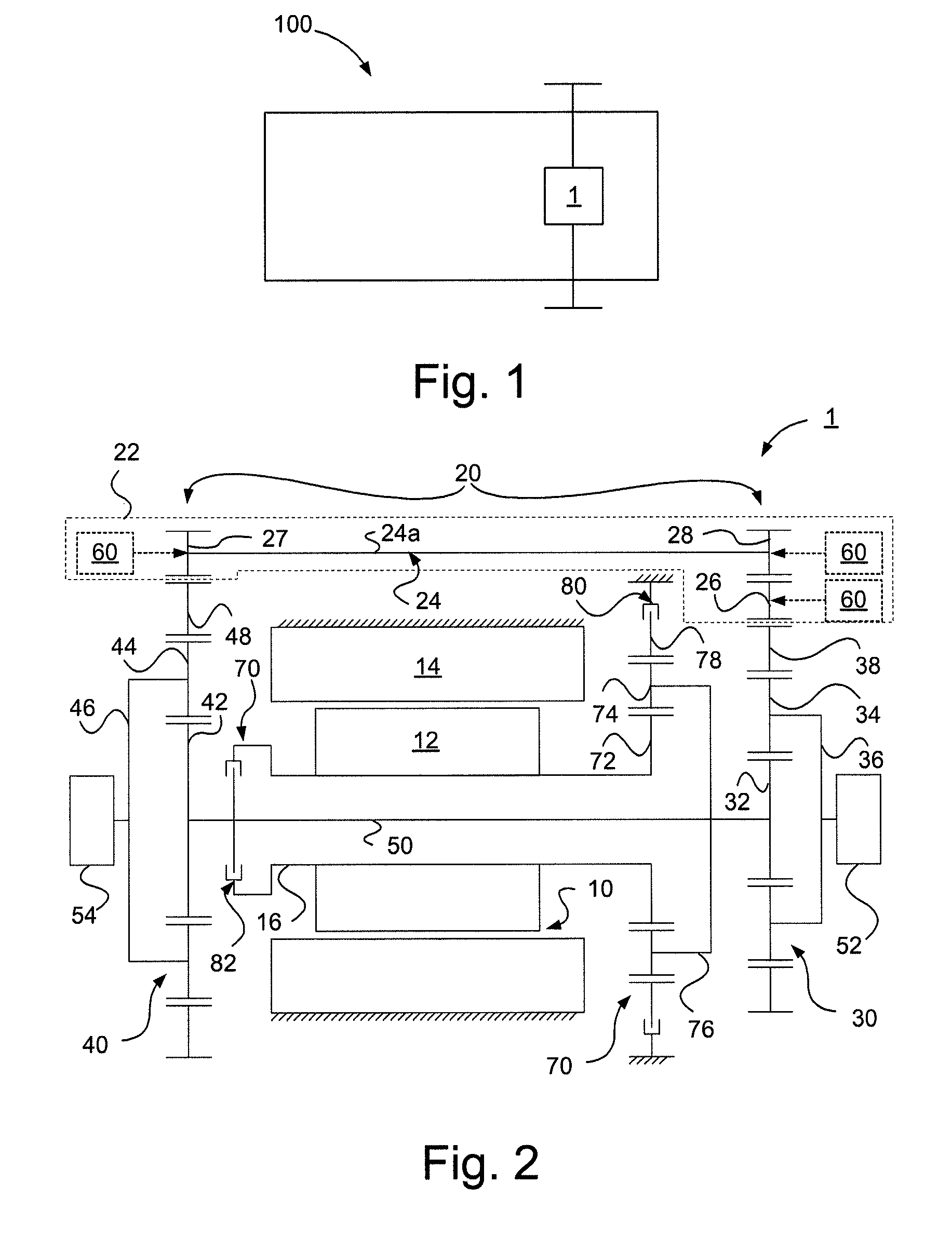
[0034]FIG. 1 schematically illustrates a motor driven unit 100 comprising an electric drive system 1 according to the present invention. Said motor driven unit 100 may be constituted by a motor vehicle such as a working vehicle.

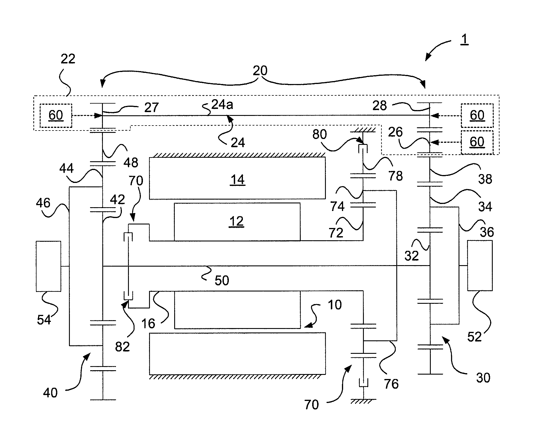
[0035]FIG. 2 schematically illustrates an electric drive system 1 according to an embodiment of the present invention. The electric drive system 1 comprises an electric motor 10 having a rotor 12 and a stator 14, said rotor 12 being connected to a drive shaft 16, said rotor 12 being arranged to rotate said drive shaft 16.

[0036]The electric drive system 1 further comprises differential means 20. Said differential means 20 comprises a first planetary gear configuration 30 and a second planetary gear configuration 40, said motor 10 being disposed between said first and second planetary gear configuration 30, 40.

[0037]The second planetary gear configuration 40 is in driving engagement with said first planetary gear configuration 30 via an output shaft 50 rotatabl...


PUM


Abstract

An electric drive system including an electric motor arranged to rotate a drive shaft. A differential includes a first planetary gear being drivingly connected to a first output assembly. A second planetary gear configuration is in driving engagement with the first planetary gear configuration via an output shaft. The second planetary configuration is drivingly connected to a second output assembly. The motor is disposed between the first and second planetary gear configuration. The first planetary gear configuration is arranged to co-act with the second planetary gear configuration so as to provide a differential function. The ring gears of the first and second planetary gear configurations are engaged via a reversing assembly for the differential function. Also, a motor driven unit, such as a motor vehicle.

Description

TECHNICAL FIELD[0001]The invention relates to an electric drive system. The invention further relates to a motor driven unit, for example a motor vehicle.BACKGROUND ART[0002]It is known to use a pair of planetary gear configurations to provide differential drive respectively to a pair of output assemblies such as ground engaging wheels or a continuous belt or track, wherein the planetary gear configurations are arranged such that their respective sun gears are driven by a common drive member or shaft. The main drive source, typically a drive shaft propelled by an internal combustion engine, may be in mesh with a ring gear of one of the planetary gear configurations to provide directionality and gear reduction. Typically, the drive source includes a rotational axis perpendicularly disposed relative to the rotational axis of a driven axle, here referred to as a cross drive.[0003]Such cross drive connections causes losses in the power transfer. An electrically driven power train where ...

Claims


Application Information

Patent Timeline
Patent Type & Authority Patents(United States)
IPC IPC(8): F16H48/30B62D11/06
CPCB60L15/20F16H48/22F16H48/10Y02T10/7275Y02T10/72Y02T10/64
Inventor KARLSSON, PONTUSKJELLMAN, HENRIKLASSILA, VIKTOR
Owner BAE SYSTEMS HAGGLUNDS AKTIEBOLAG
Why Eureka
Try Eureka