Prosthetic valve with spacing member
a technology of prosthetic valves and spacing members, applied in the field of prosthetic valves, can solve the problems of loss of effectiveness, physical manifestations and pathologies, and the insufficientness of venous valves,
- Summary
- Abstract
- Description
- Claims
- Application Information
AI Technical Summary
Benefits of technology
Problems solved by technology
Method used
Image

Examples
Embodiment Construction
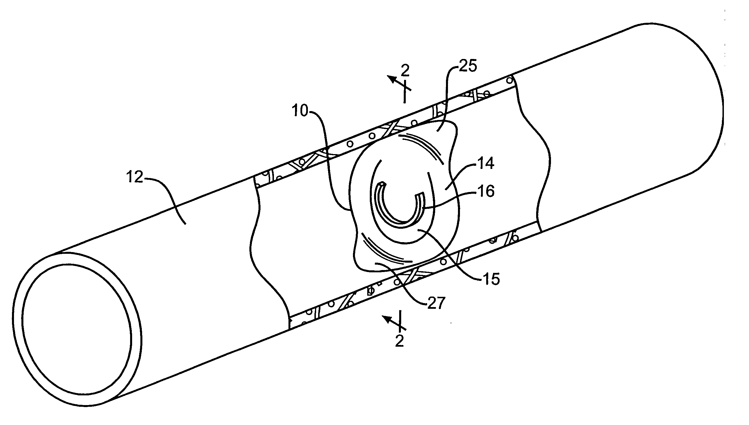
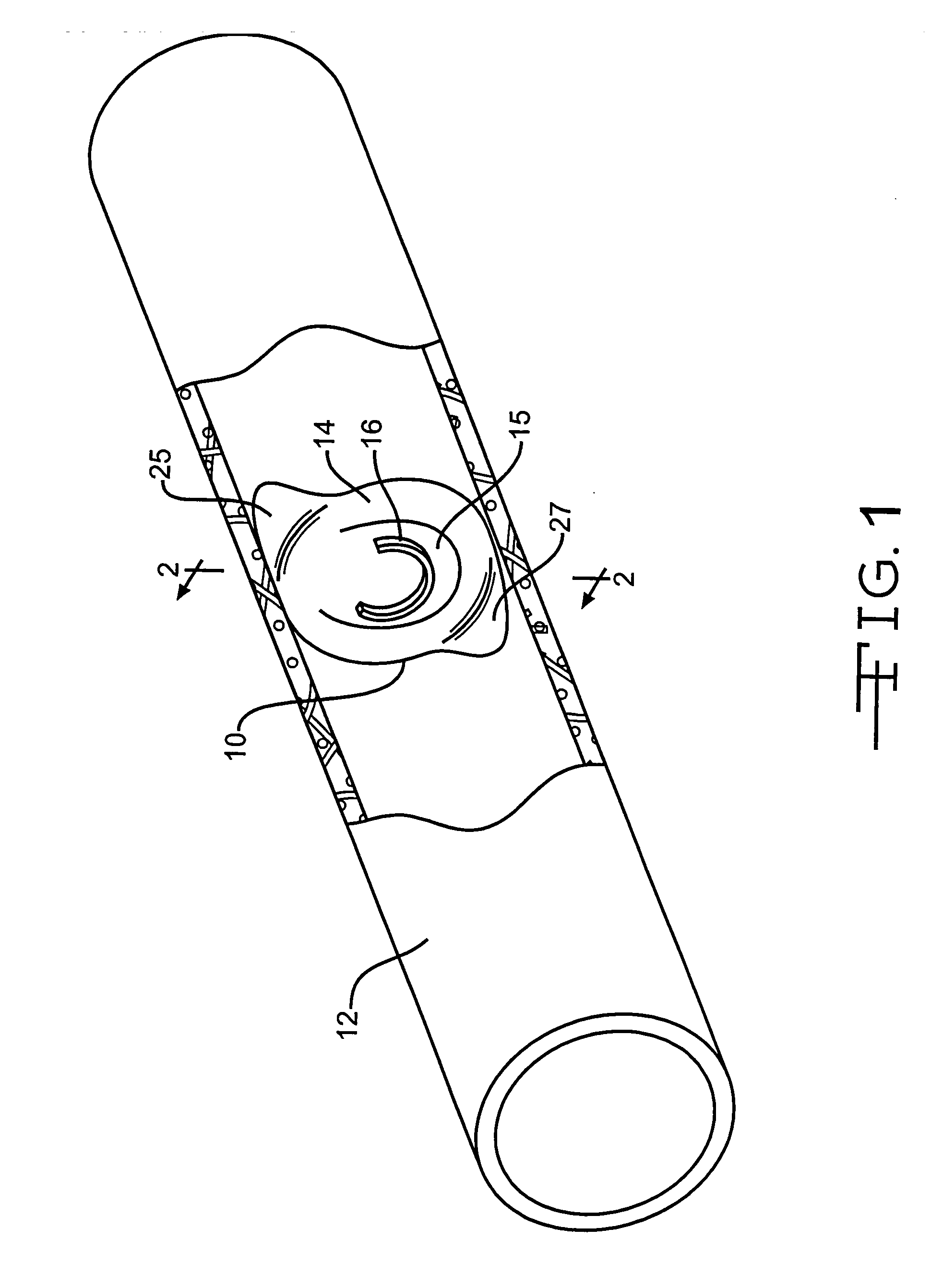
[0010] The invention provides prosthetic valves that include one or more elements that protect a moveable portion of the valve from adherence and / or incorporation into a tissue, such as a vessel wall, and / or from mechanical interaction with another structural component of the valve, such as a portion of a support frame.
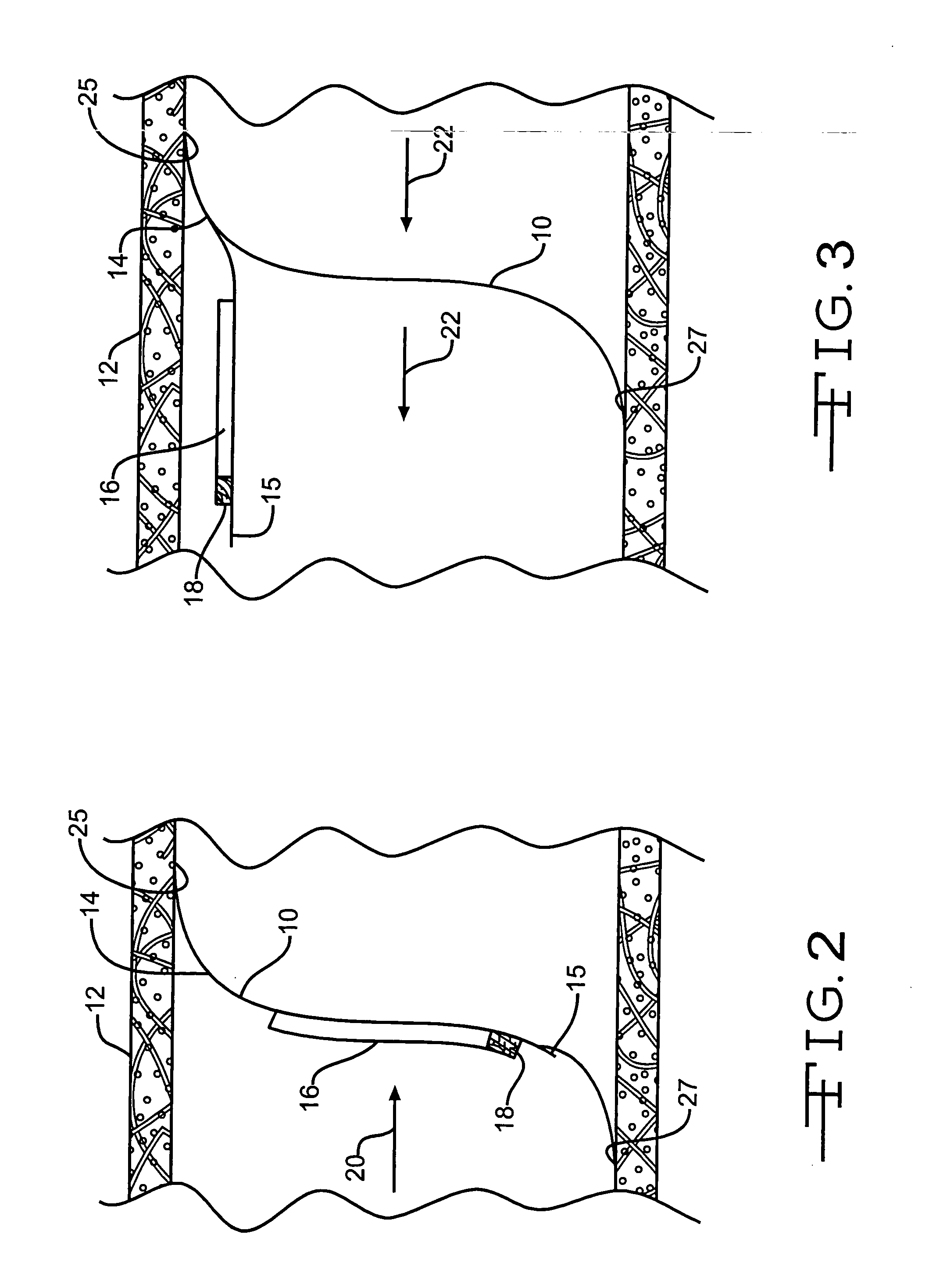
[0011] The invention provides prosthetic valves for implantation in a body vessel. In one embodiment, a prosthetic valve according to the invention comprises a valve member comprising a valve portion movable between first and second positions. A spacing member is disposed on the valve portion and has a predetermined thickness. The spacing member protects the valve portion from contact with the wall of the body vessel in which the prosthetic vessel is implanted.
[0012] In another embodiment, a prosthetic valve according to the invention comprises an expandable support frame and a valve member attached to the support frame. The valve member comprises a valve portion mo...
PUM
| Property | Measurement | Unit |
|---|---|---|
| Thickness | aaaaa | aaaaa |
| Bioabsorbable | aaaaa | aaaaa |
| Bioactive | aaaaa | aaaaa |
Abstract
Description
Claims
Application Information
 - R&D Engineer
- R&D Manager
- IP Professional
- Industry Leading Data Capabilities
- Powerful AI technology
- Patent DNA Extraction
Browse by: Latest US Patents, China's latest patents, Technical Efficacy Thesaurus, Application Domain, Technology Topic.
© 2024 PatSnap. All rights reserved.Legal|Privacy policy|Modern Slavery Act Transparency Statement|Sitemap