

Machine management system and message server used for machine management
a machine management system and message server technology, applied in the field of machine management system, can solve the problems of user inability to see on the screen, abnormal lower level not displayed on the screen, etc., and achieve the effect of preventing oversight of machine managemen
- Summary
- Abstract
- Description
- Claims
- Application Information
AI Technical Summary
Benefits of technology
Problems solved by technology
Method used
Image

Examples
first embodiment
(A) First Embodiment
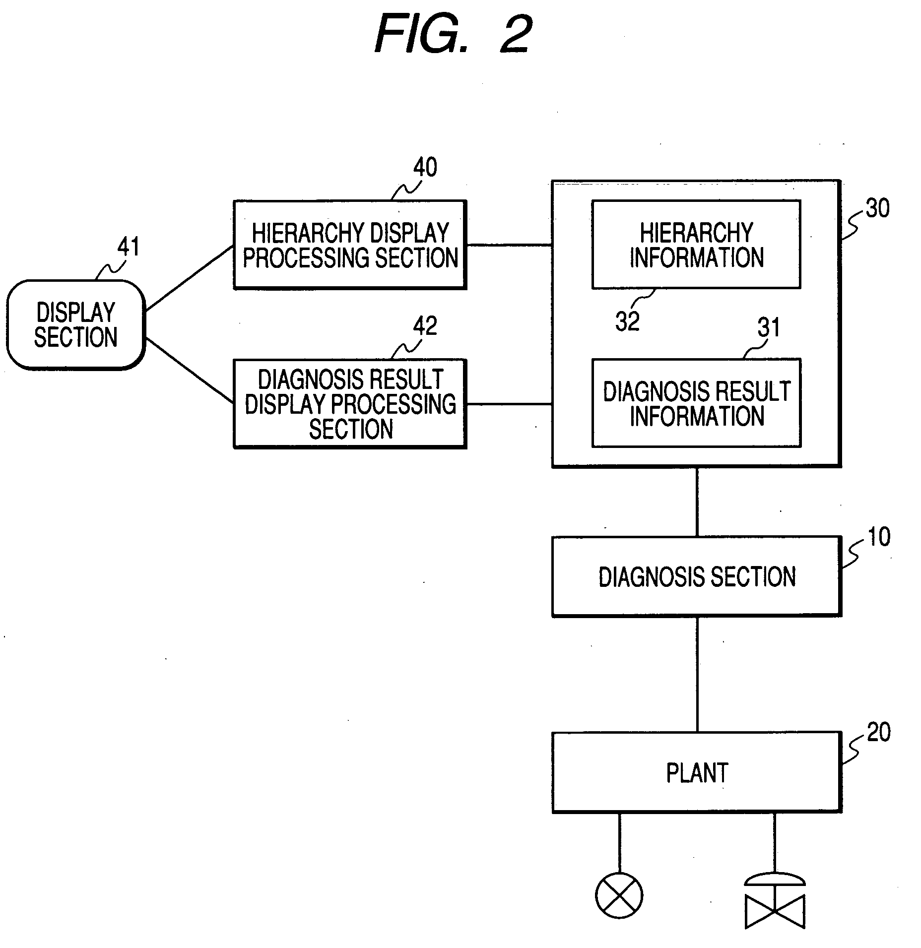
[0029]FIG. 2 is a block diagram to show a first embodiment of the invention.
[0030] In FIG. 2, a diagnosis section 10 diagnoses each machine existing in a plant 20. The plant 20 is a plant of petrochemistry, steel, paper and pulp, foods, chemicals, electric power, etc., for example.
[0031] The machines existing in the plant 20 are sensor machines for detecting the process values of temperature, pressure, liquid level, etc., valve positioners for controlling valves, and the like.
[0032] A storage section 30 stores diagnosis result information 31 of the diagnosis section 10, hierarchy information 32 systematically indicating a plant hierarchy as a tree structure, and the like.
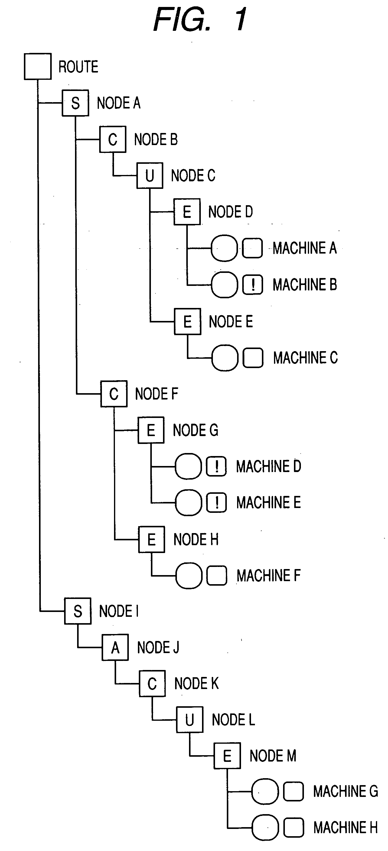
[0033] A hierarchy display processing section 40 classifies the machines existing in the plant 20 under a multilevel hierarchy and processes to display them on a screen of a display section 41 as a tree structure.
[0034] A diagnosis result display processing section 42 processes to display th...
second embodiment
(B) Second Embodiment
[0057]FIG. 4 is a block diagram to show a second embodiment of the invention. Parts identical with those previously described with reference to FIG. 2 are denoted by the same reference numerals in FIG. 4.
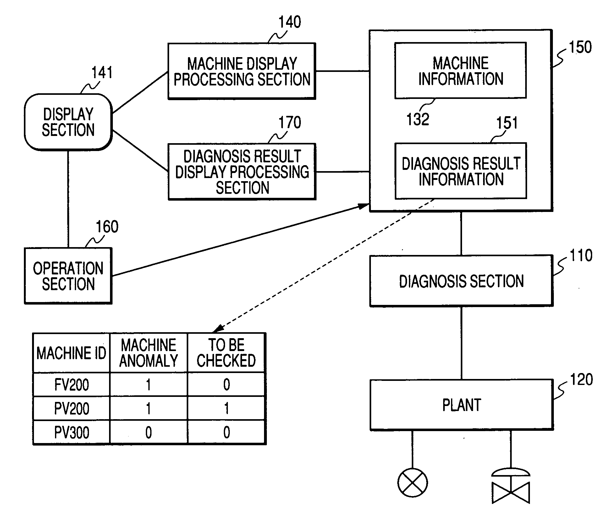
[0058] In FIG. 4, a diagnosis result display processing section 50 processes to display the level of an alarm occurring in each machine displayed on a screen and also processes to display the alarm level at the higher level of the plant hierarchy to which the machines not displayed on the screen are connected.
[0059] The diagnosis result display processing section 50 processes to display the level of an alarm occurring in each machine displayed on a screen and also displays the highest level of the alarm levels of all machines containing the machines not displayed at the lower levels of the plant hierarchy displayed on the screen.
[0060] A selection display processing section 51 processes to selectively display the machines whose alarm level is equal to or grea...
third embodiment
(C) Third Embodiment
[0068]FIG. 6 is a block diagram to show a third embodiment of the invention.
[0069] In FIG. 6, a diagnosis result display processing section 60 processes to display the state of each node displayed on a screen and also displays a summary of the states of all nodes containing the nodes not displayed at the lower levels than an intermediate hierarchy level.
[0070] In a manufacturing line, for example, “remaining amount of raw material” is linked with “state.” In this case, “fact that remaining amount becomes small” or “fact that remaining amount has run out” can be represented as “state.”“Fact that remaining amount becomes small” or “fact that remaining amount has run out” is set to “special state,” whereby the remaining amount of the raw material in the manufacturing line can be represented as a tree structure.
[0071] In the above-described embodiment, the alarm state and the abnormal state are displayed in an easy-to-understand manner.
[0072] In contrast, the nor...
PUM
 Abstract
Description
Claims
Application Information