

Clasp for jewelry
a technology for clasps and jewelry, applied in the field of clasps, can solve the problems of conventional clasps failing to draw the attention of users with respect to functions, and users might have so as to prevent users from having a pain in their fingers
- Summary
- Abstract
- Description
- Claims
- Application Information
AI Technical Summary
Benefits of technology
Problems solved by technology
Method used
Image

Examples
first embodiment
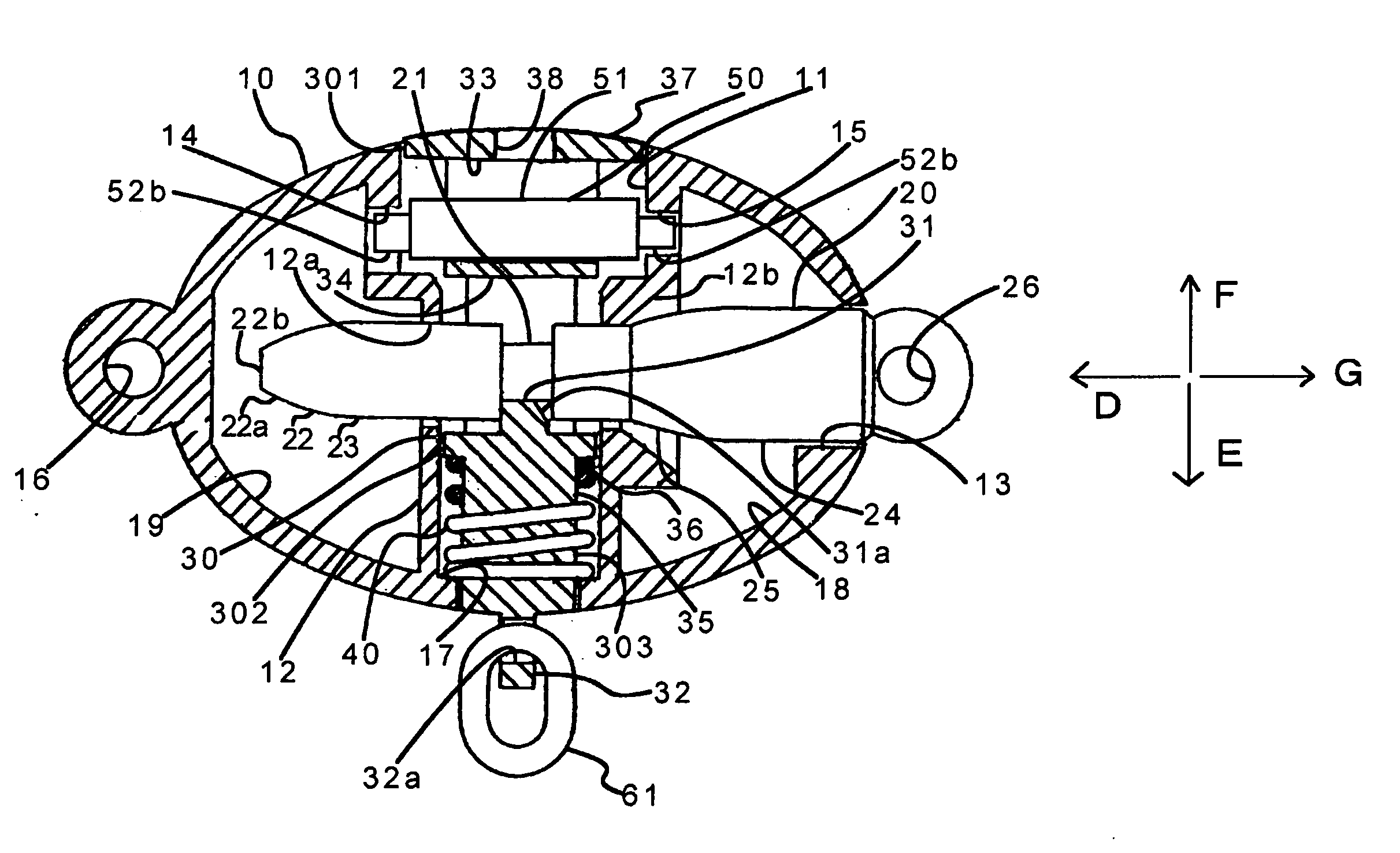
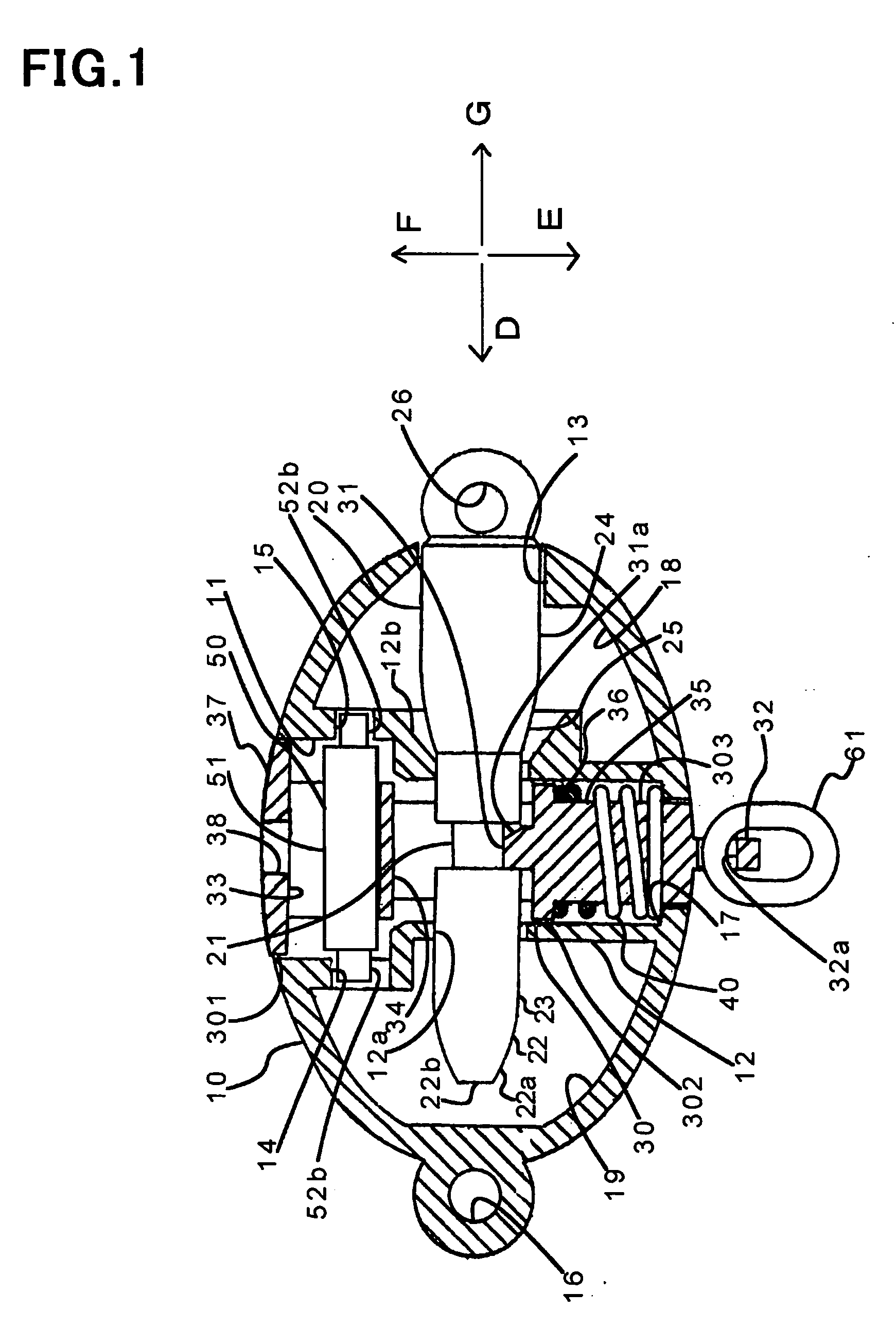
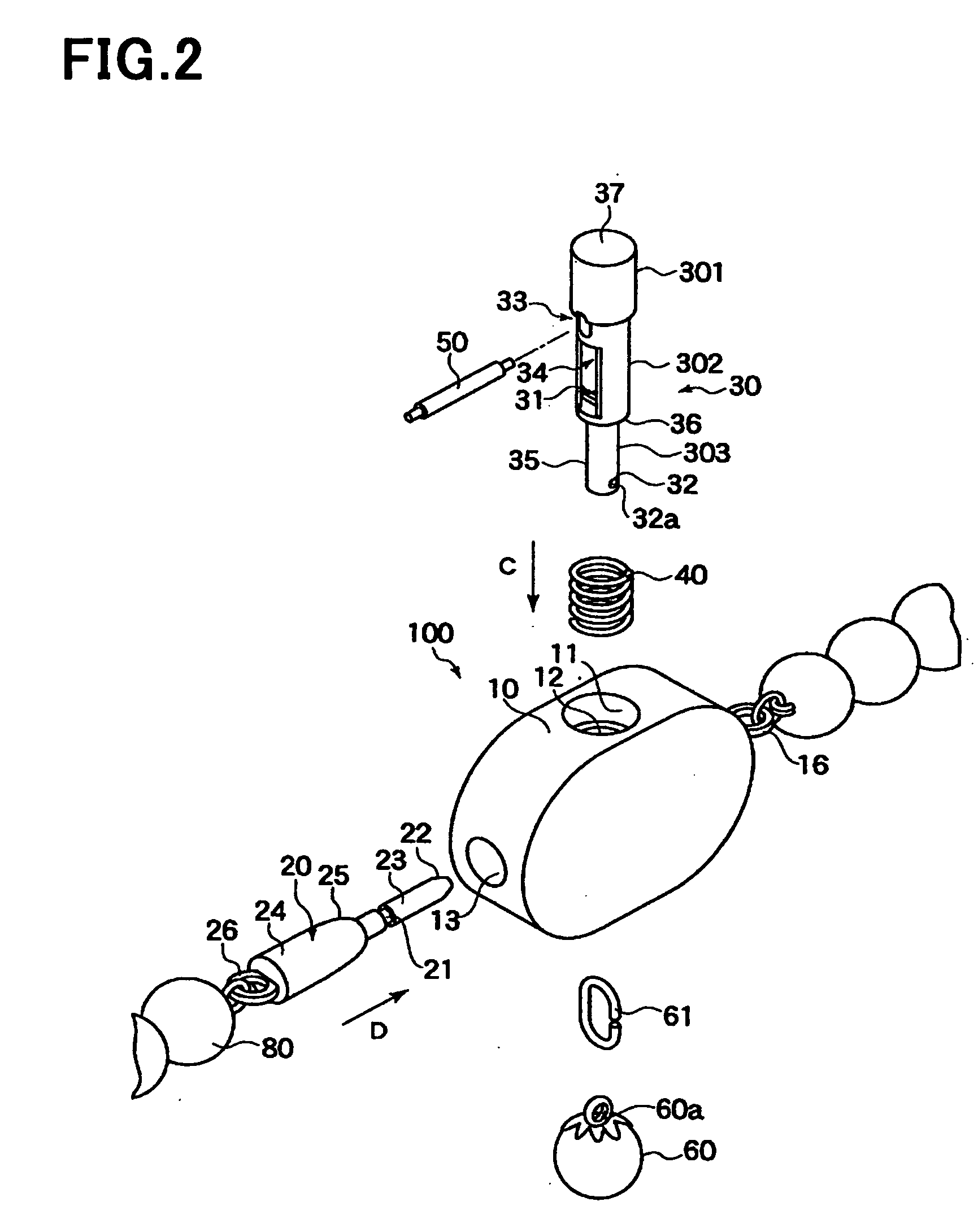
[0064]FIG. 1 is a cross-sectional view of a clasp 100 in accordance with the first embodiment, and FIG. 2 is an exploded perspective view of the clasp 100. A horizontal positional relation in FIG. 2 is just opposite to FIG. 1.
[0065] As illustrated in FIGS. 1 and 2, the clasp 100 is comprised of a body 10, a pin 20 to be inserted into the body 10, a stopper 31 engaging to the pin 20 having been inserted into the body 10 to keep the pin 20 engaged to the body 10, and a releaser 32 which ceases engagement of the stopper 31 with the pin 20 to thereby release the pin 20 from the body 10.
[0066] The stopper 31 and the releaser 32 are formed integrally with each other. Specifically, the stopper 31 defines a part of a cylinder 30, and the releaser 32 also defines a part of the cylinder 30. The cylinder 30 is disposed in the body 10 so as to be movable relative to the body 10.
[0067] The clasp 100 further includes a coil spring 40 energizing the cylinder 30, and a pin 50 preventing the coil...
second embodiment
[0136]FIG. 5 is a cross-sectional view of a clasp 200 in accordance with the second embodiment of the present invention.
[0137] Hereinbelow is explained the clasp 200 with reference to FIG. 5.
[0138] The clasp 200 is structurally different from the clasp 100 in accordance with the first embodiment only in what is explained later. Hence, parts or elements that correspond to clasp 100 have been provided with the same reference numerals, and are not explained.
[0139] As illustrated in FIG. 5, the end 37 in the second embodiment is formed thicker than the end 37 in the first embodiment, and projects outwardly beyond the body 10 accordingly. Thus, the end 37 defines a second releaser.
[0140] Specifically, it is possible to release the pin 20 from the stopper 3.1 by pulling the releaser 32 in the direction E and pushing the end 37 acting as a second releaser in the direction E. As an alternative, the pin 20 can be released from the stopper 31 by pushing the end 37 in the direction E or pu...
third embodiment
[0152]FIG. 6 is a cross-sectional view of a clasp 300 in accordance with the third embodiment of the present invention.
[0153] Hereinbelow is explained the clasp 300 with reference to FIG. 6.
[0154] The clasp 300 is structurally different from the clasp 100 in accordance with the first embodiment only in what is explained later. Hence, parts or elements that correspond to clasp 100 have been provided with the same reference numerals, and are not explained.
[0155] The pin 50 in the first and second embodiments is comprised of such a spring bar as illustrated in FIG. 3. The pin 50 in the third embodiment is comprised of such a spring pin as illustrated in FIG. 7.
[0156] The pin 50 illustrated in FIG. 7 is comprised of a cylindrical body 55 formed with a cut-out 56 extending longitudinally thereof. The cylindrical body 55 has chamfered ends 57 so as to be thin at opposite ends.
[0157] The pin 50 is fixedly inserted into a hole (for instance, a later mentioned hole 311), if the hole has...
PUM
 Abstract
Description
Claims
Application Information