Target grip apparatus for a firearm

Inactive Publication Date: 2005-09-01
DANAS GREGORY A
View PDF23 Cites 29 Cited by
  • Summary
  • Abstract
  • Description
  • Claims
  • Application Information

AI Technical Summary

Benefits of technology

[0011] Accordingly, it is therefore an object of this invention to provide various size contoured gr

Problems solved by technology

However, the handgun grip does not provide for the adjustment or positioning of the distal portion of the trigger finger, nor does it provide for the desired positioning of a right angle of the trigger finger to the trigger.
However, the weapon grip does not provide for the adjustable placement of a trigger finger, relati

Method used


Image

  • Target grip apparatus for a firearm
  • Target grip apparatus for a firearm
  • Target grip apparatus for a firearm

Examples


first embodiment

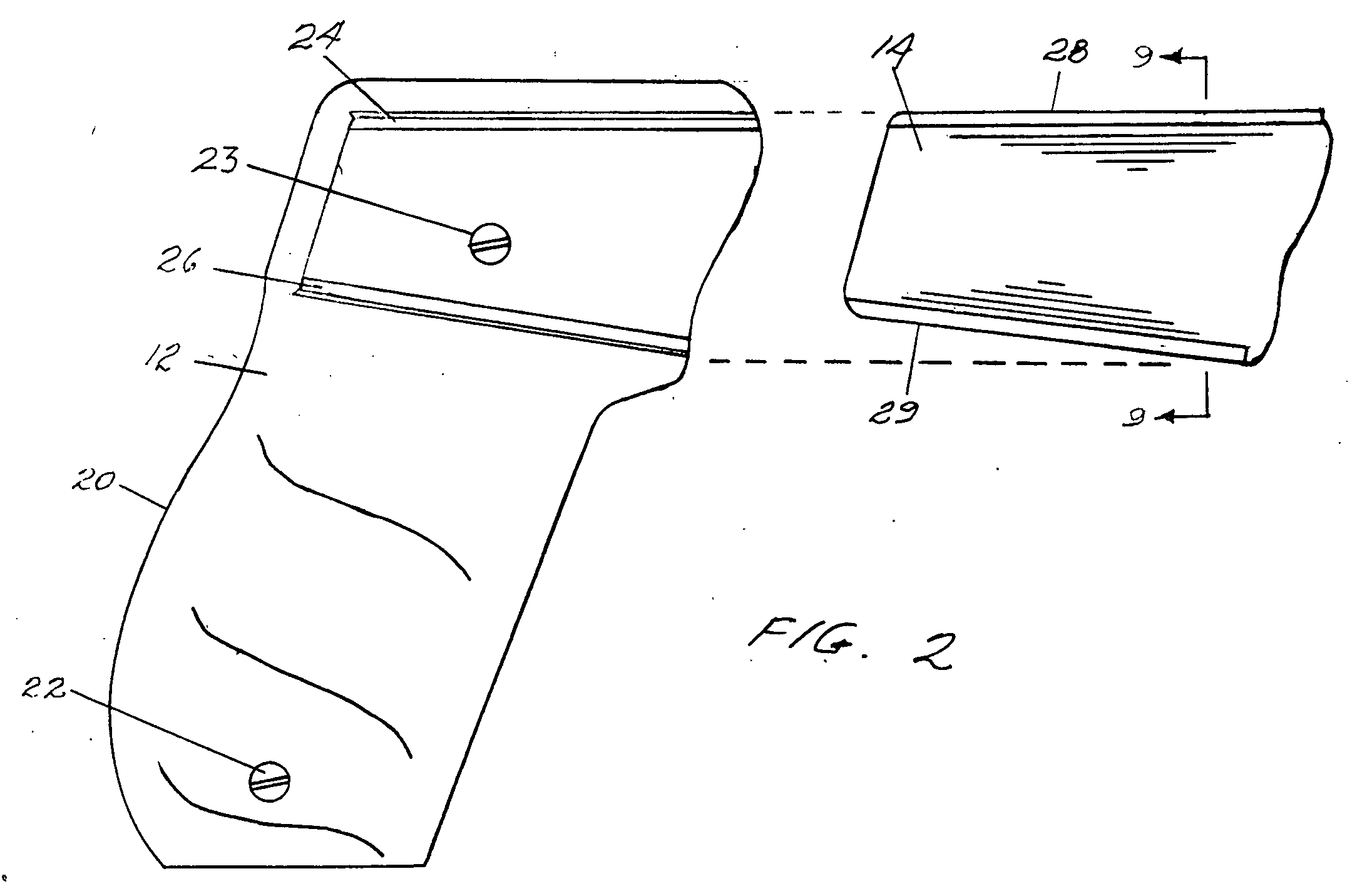
[0054] Referring to FIG. 2, an exploded view of the side panel 12 with trigger finger target grip extender insert 14 is shown comprising wings 28, 29 on the top and bottom edges of the insert 14 for mating with receiving channels 24, 26 on the side panel 12 and for guiding the insert 14 in and out of the side panel 12 and for securing the trigger finger target extender insert 14 within the side panel 12. The right side panel 12 is retained on the side of the frame 20 by two screws 22, 23.

[0055] Referring to FIG. 9, a cross-sectional view is shown of the trigger finger target grip extender insert 14 with wings 28, 29 for mating with the receiving channels 24, 26 within the side panel 12.

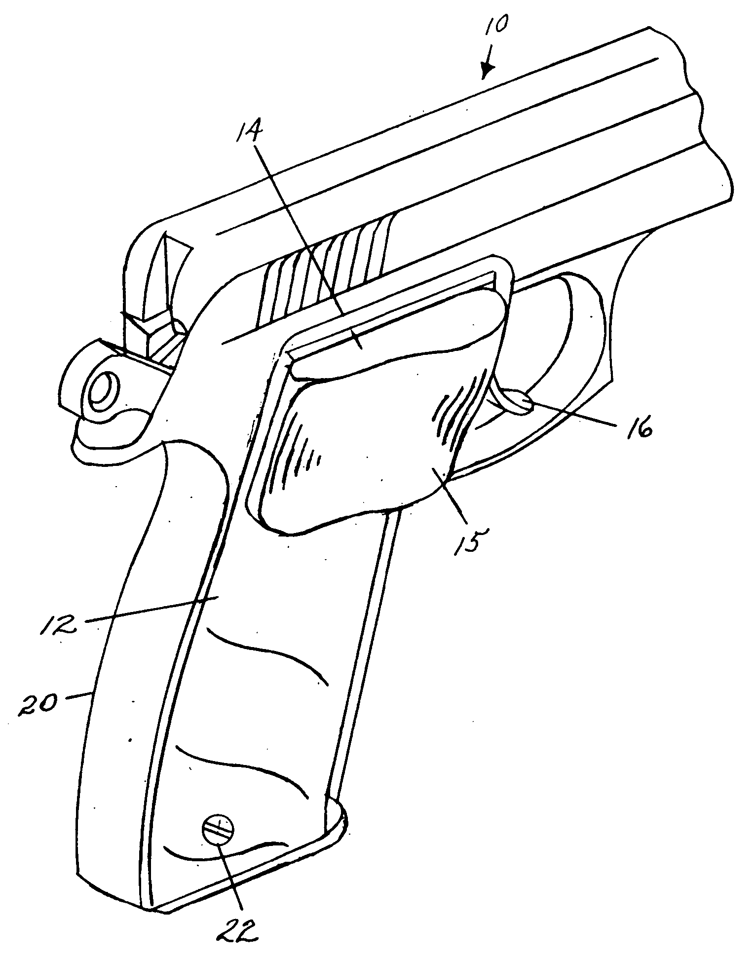
[0056] Referring to FIG. 3, an isometric view of the side panel 12 is shown having the trigger finger target grip extender insert 14 for positioning a right hand trigger finger on the trigger 16. The side extension 15 is shown extending outward and toward the trigger 16 to enable the distal portion o...

second embodiment

[0058] Referring now to FIG. 5, an exploded view is shown of a right side panel 12 having a target trigger grip extender insert 30 which comprises a clip 32 at one side and wings 31, 33 on the top and bottom of the extender insert 30 for insertion into channels 24, 26 of the side panel 12. The insert 30 slides from right to left and the clip 32 is secured within the side panel 12. Pressing on an embossed area 34 of the insert 30 causes the insert 30 to slide out for removal.

third embodiment

[0059] Referring to FIG. 6, an exploded view is shown of a left side panel 40 having a target grip extender insert 42 which comprises a clip 44 at one side and wings 41,43 on the top and bottom of the extender insert 42 for insertion into channels 48, 49. The insert 42 slides from left to right and the clip 44 is secured within the side panel 40. Pressing on an embossed area 46 of the insert 42 causes the insert 42 to slide out for removal.


PUM


Abstract

A target grip for a firearm comprising fixed and removable trigger finger extenders for a side panel of the firearm for enabling the distal portion of a user's trigger finger to contact a trigger at an angle approximately perpendicular to the trigger for more shooting accuracy and consistency. Various size target grip trigger finger extenders are provided for the side panel of the firearm until the proper size extender is found by a user. In one embodiment, the target grip extender is secured by a locking device positioned within the extender. In another embodiment, the trigger finger extender is an integral part of the side panel. The side panel may be attached to the side of a firearm by screws or by an adhesive. In a further embodiment, the trigger finger extender is an integral part of a sleeve that slips over the frame of the firearm.

Description

CROSS-REFERENCE TO RELATED APPLICATIONS [0001] This application is a Continuation-In-Part of prior application Ser. No. 10 / 404,930, filed Apr. 1, 2003, now pending.BACKGROUND OF THE INVENTION [0002] 1. Field of the Invention [0003] This invention relates to a firearm grip and in particular to a pistol target grip comprising fixed and removable trigger finger extenders on a side panel of the body of the firearm grip. [0004] 2. Description of Related Art [0005] Many types of grips have been devised for attachment to firearms or pistols enabling a user to better hold and aim a firearm, or to reduce recoil or otherwise improve the comfort when the firearm is held and fired to achieve consistent accuracy. The use of elastomers in the grip assembly provides for a better “feel” in the user's hand and may provide a certain amount of bulk or sizing to otherwise standard factory produced grips. The following listed U.S. patents are examples of firearm grips. [0006] U.S. Pat. No. 5,621,997 iss...

Claims


Application Information

Patent Timeline
IPC IPC(8): F41C23/10
CPCF41C23/10
Inventor DANAS, GREGORY A.
Owner DANAS GREGORY A
Why Eureka
Try Eureka