Slot channel overhead storage platform

Active Publication Date: 2005-09-01
RYBERG DAVID L
View PDF26 Cites 39 Cited by
  • Summary
  • Abstract
  • Description
  • Claims
  • Application Information

AI Technical Summary

Benefits of technology

[0012] A solution to the above has been devised. An overhead storage platform comprised of a deck supported by a plurality of slot channel beams is provided. Each slot channel beam has a slot channel formed along a length of the slot channel beam and is affixed to an ov

Problems solved by technology

Moreover, in the preferred embodiment the vertical supports are adjustable in length as well, not only allowing adjustment in the length of the vertical supports to accommodate overhead ceilings th

Method used


Image

  • Slot channel overhead storage platform
  • Slot channel overhead storage platform
  • Slot channel overhead storage platform

Examples


Embodiment Construction

[0029] The following description, and the figures to which it refers, are provided for the purpose of describing examples and specific embodiments of the invention only and are not intended to exhaustively describe all possible examples and embodiments of the invention.

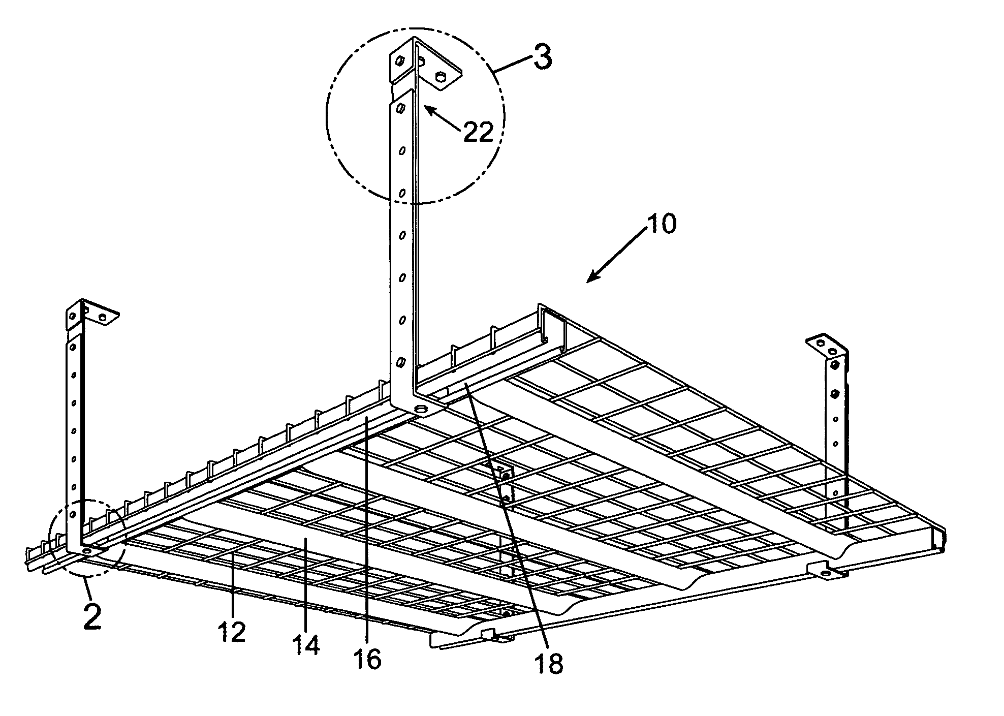
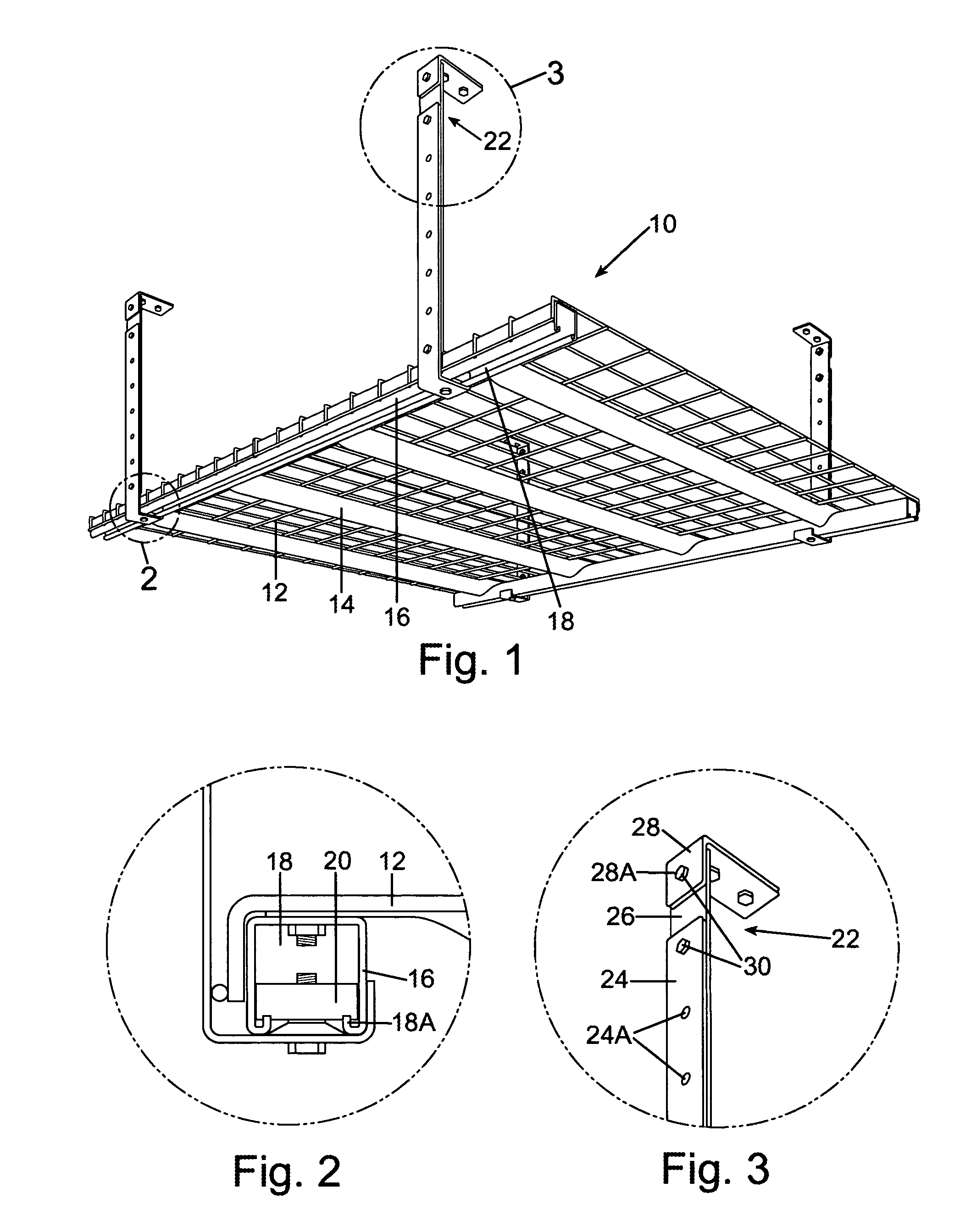
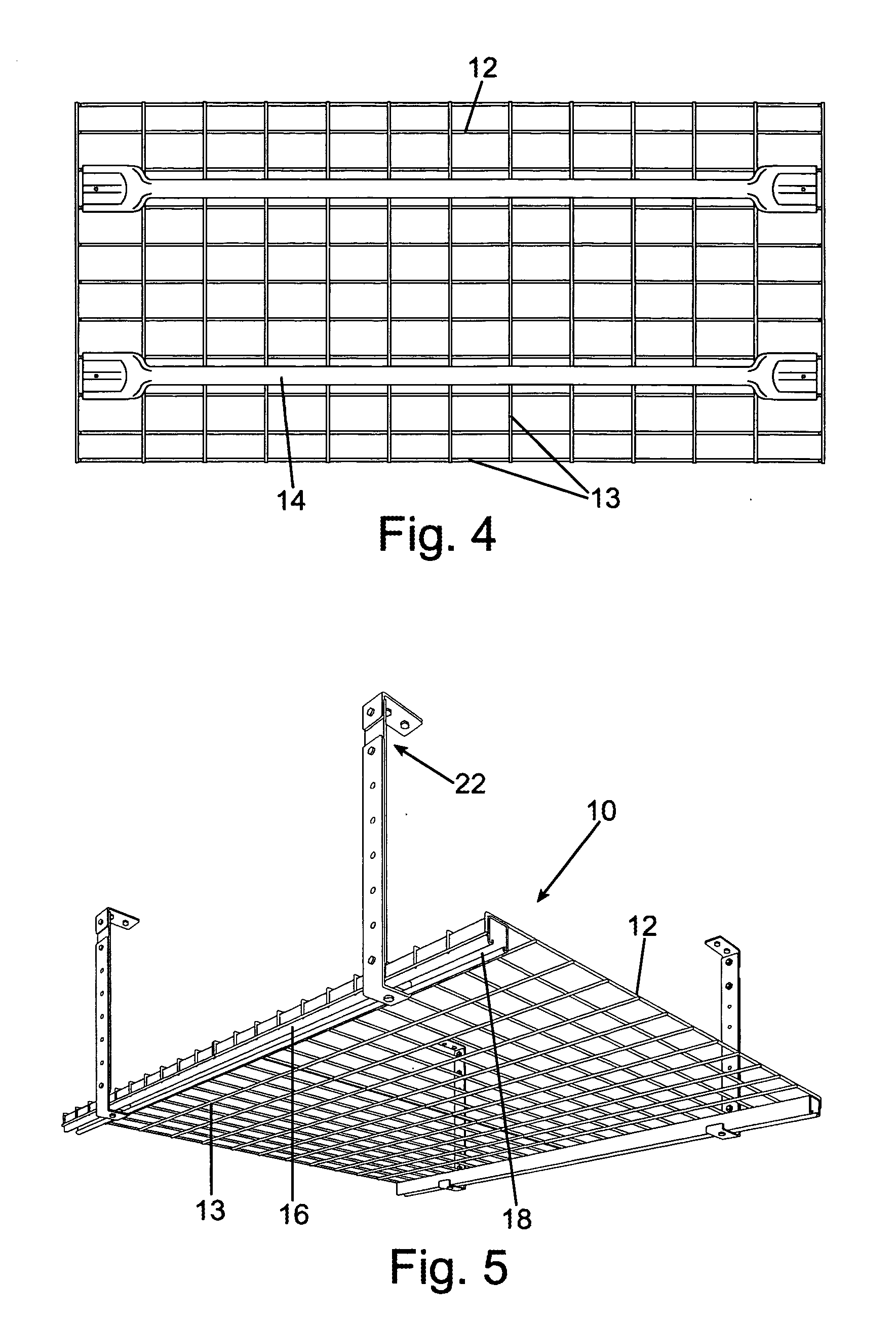
[0030] Referring now to FIG. 1, a first embodiment of the overhead storage platform 10 of the present invention is shown. A deck 12, here shown as a wire grid, rests upon traverse support beams 14 that hold the slot channel beams 16 apart at a relative fixed distance. The traverse support beams 14 may also be used to support the deck 12 itself.

[0031] Each slot channel beam 16 includes a slot channel 18 formed along the length of the slot channel beam 16. In the preferred embodiment the slot channel beam is formed from a generally U-shaped member having an opening along the entire length of one side of the slot channel beam 16. Referring also to FIG. 2 a detail view of the slot channel 18 of slot channel beam 16 is s...


PUM


Abstract

An overhead storage platform supported by vertical members that includes slotted support beams supporting the platform deck. The vertical support members are affixed to a ceiling or other overhead structure on one end and to the slotted support beams on the other end, where they are adapted to be adjustably moved and affixed within a slot channel in the slotted support beams. The vertical support members can be adjustable in length as well. These two adjustment dimensions allow more adaptability to affixing the platform to overhead supports of varying configurations. Multiple platforms may be abutted to provide a larger and substantially continuous platform deck.

Description

RELATED APPLICATIONS [0001] This patent application claims priority to U.S. Provisional Patent Application Ser. No. 60 / 667,255 filed on Apr. 1, 2005, entitled Slot Channel Overhead Storage Platform.FIELD OF THE INVENTION [0002] This invention relates to overhead storage racks and more particularly to a method and apparatus for employing a more utilitarian overhead rack. BACKGROUND OF THE INVENTION [0003] There are many variations in overhead storage platforms, for example platforms that include a deck of manufactured rack that might be used for extra storage in a residential garage or for inventory in a retail establishment. Platforms have been affixed to ceilings or other overhead structures through history. In its most rudimentary form a rack or other deck is simply affixed to separate vertical members extending between the platform and the overhead structure, which in its simplest form this can be made with lumber. Other configurations might include a cradle configuration, with s...

Claims


Application Information

Patent Timeline
IPC IPC(8): A47B5/00A47B96/02F16B37/04
CPCF16B37/045A47B96/024
Inventor RYBERG, DAVID L.
Owner RYBERG DAVID L
Why Eureka
Try Eureka