Semi-automatic-firing, compressed-gas gun

a gas gun and semi-automatic technology, applied in the field of paintball guns, can solve the problems of affecting the overall sense of balance, operation, utility, and segregation of gas supply and launcher (gun), and achieve the effect of distributing a limited amount of propellan

Inactive Publication Date: 2005-09-01
TIBERIUS BENJAMIN T +2
View PDF76 Cites 39 Cited by
  • Summary
  • Abstract
  • Description
  • Claims
  • Application Information

AI Technical Summary

Benefits of technology

[0019] It is an object of the invention to provide careful control of gas discharge from a propellant reservoir in order to reduce the requirements for propellant, and thus reduce the size of a propellant source required for an apparatus and method in accordance with the invention.
[0024] However, a change in air pressure may result in a chill inside the gun. That is, rapidly expanding gases left behind within the gun, may chill seals, or condense vapors, resulting in failure of operations of a gun. Stable thermodynamics may be achieved by minimizing the number of pressure drops to which the various chambers of a gun may be exposed. Accordingly, in one embodiment, the magazine may be handled as a unit, but the projectile magazine may be separated at will. Accordingly, the propellant portion and the ammunition portions may be loaded together, but one portion of the load (e.g. projectiles, propellant) may be loaded while leaving the other unmolested.
[0027] A magazine may include a receiver for holding a canister of propellant as a source of energy for launching projectiles. The propellant canister may be resealable by a valving system, thus tolerating removal without losing the charge of propellant in the canister. A series of valves, poppets, seals, springs, and the like, as well as a network of passages, may guide propellant gases from a magazine to the action of the gun. In certain embodiments, a head seal and tail seal may seal the valving portion or rod associated with a bolt.
[0028] Meanwhile, a trigger may actuate the bolt, launching both the bolt and its valving mechanism for a brief excursion into the chamber of the gun. As the bolt moves forward, the valving mechanism can shut off any further flow, thus discharging a limited amount of propellant with each shot. The trigger mechanism may include a simple release, but may include a comparatively sophisticated sear and latching mechanism for retaining the bolt in a ready-to-fire position. The sear may be selectively released by a trigger actuated by a user. Various spring mechanisms may return the sear to a ready-to-fire position, capturing the bolt upon return of the bolt from a fired position.

Problems solved by technology

Guns are carried in a manner similar to actual weapons, but typically cannot be fired as such.
Meanwhile, a rather unwieldy canister containing compressed gas is carried on a belt, pack, or the like, by a user, to be released in a stream by a trigger.
Very little control is available over the expenditure of paintballs and compressed gas.
Moreover, accuracy, conservation of ammunition, handling, and the like, are not similar to the same functions for conventional weapons.
Moreover, the segregation of the gas supply and launcher (gun) tends to interfere with the overall sense of balance, operation, utility, aiming, and the like for paintball weapons.

Method used


Image

  • Semi-automatic-firing, compressed-gas gun
  • Semi-automatic-firing, compressed-gas gun
  • Semi-automatic-firing, compressed-gas gun

Examples


Embodiment Construction

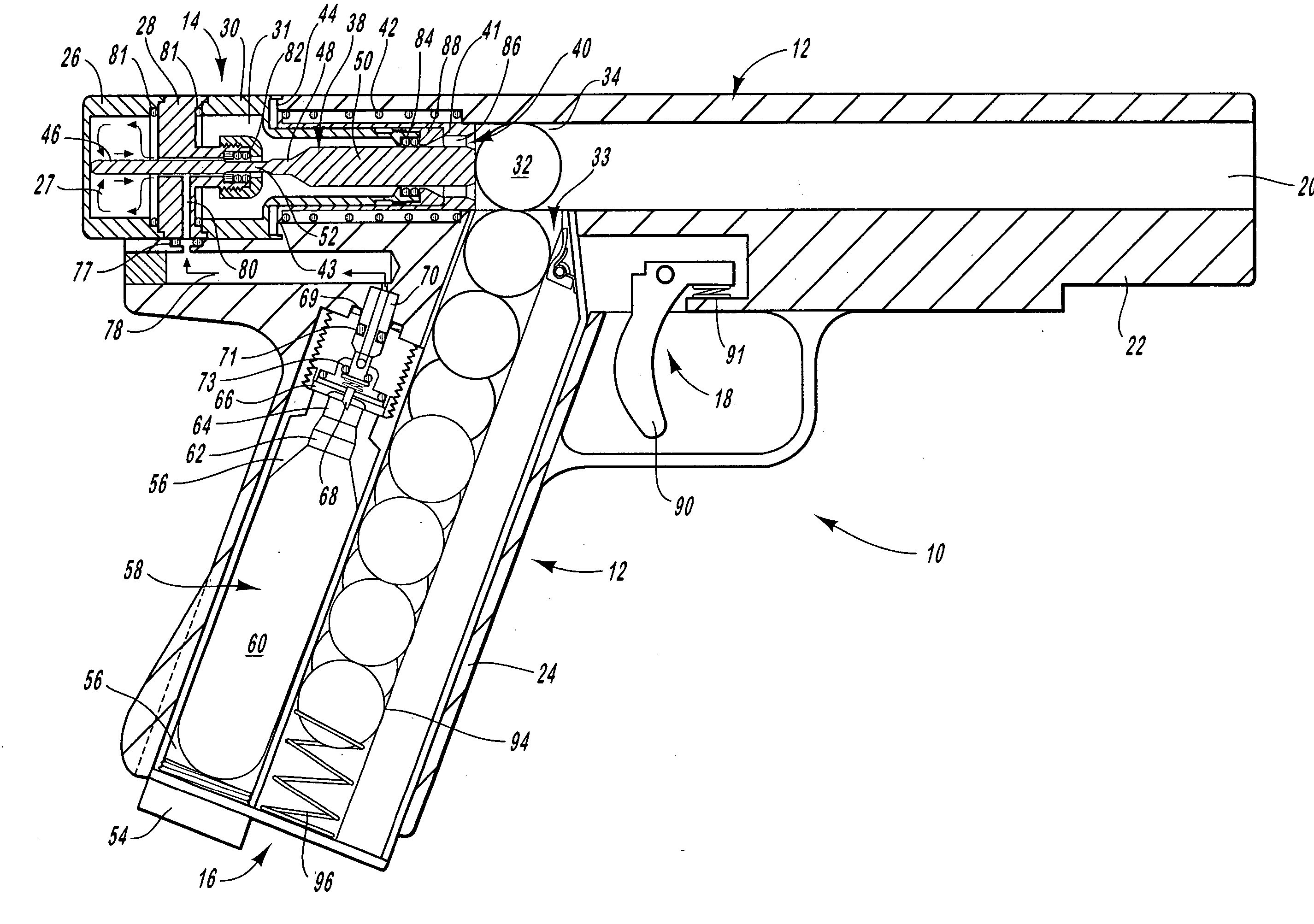
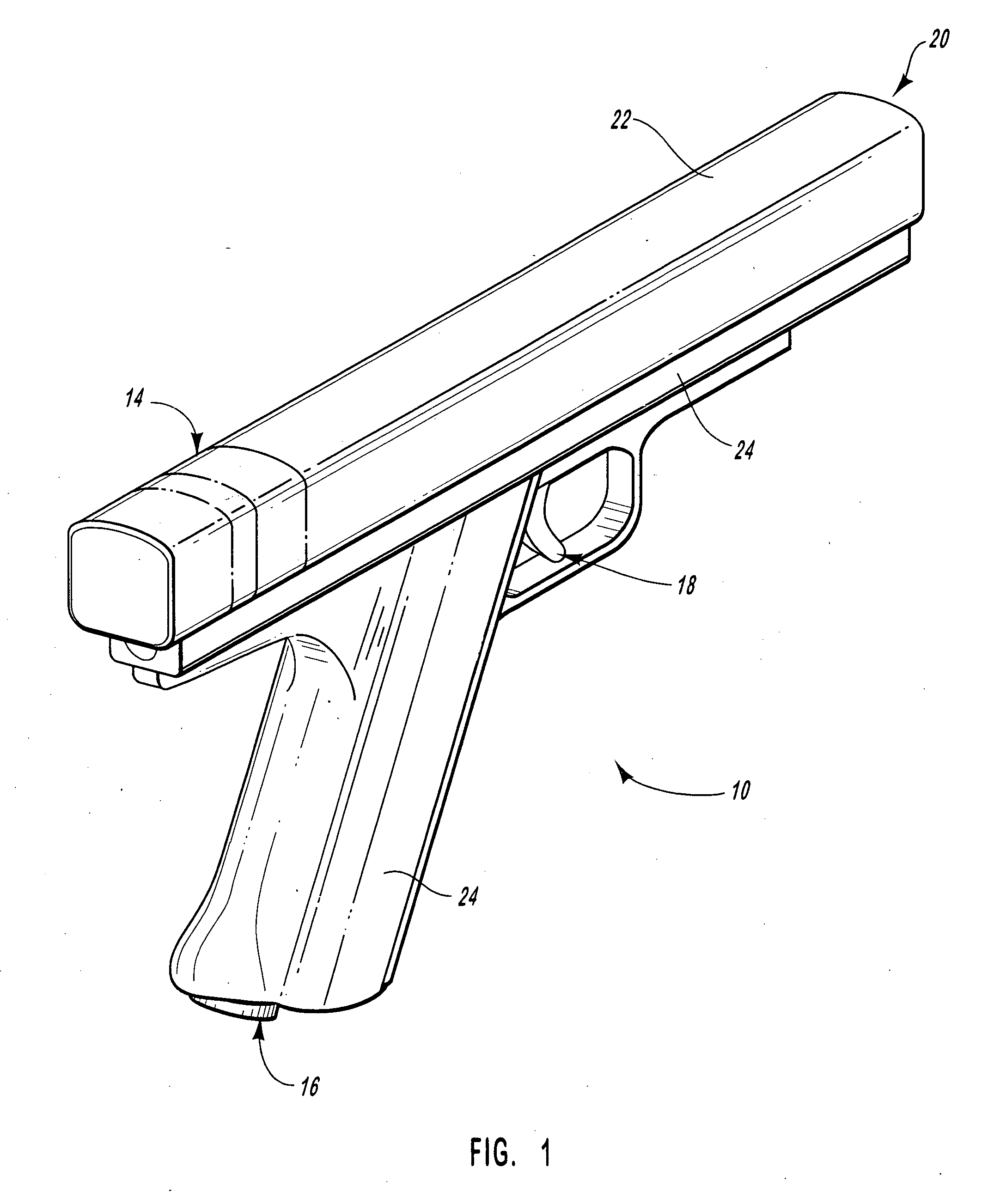
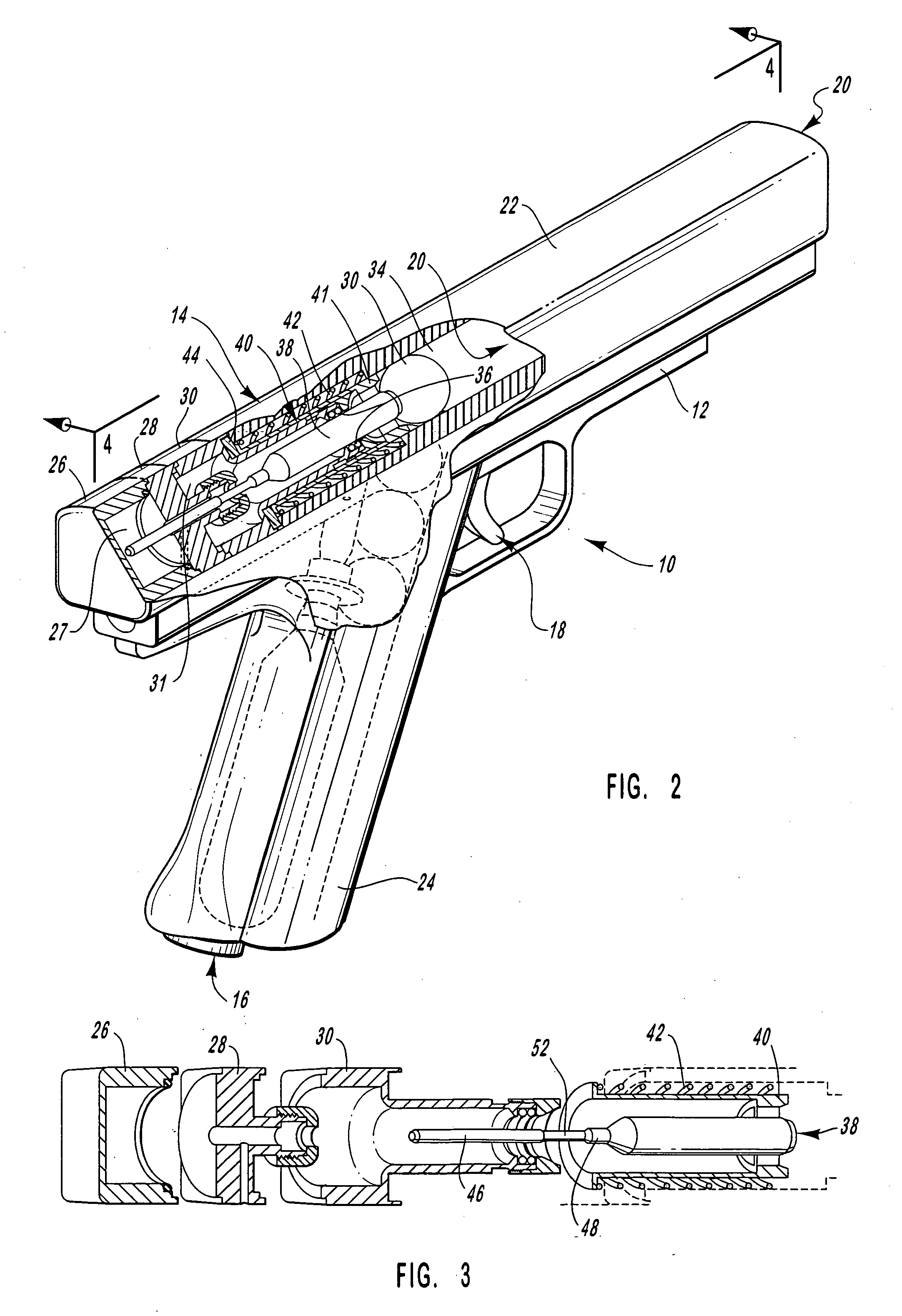
[0050] It will be readily understood that the components of the present invention, as generally described and illustrated in the Figures herein, could be arranged and designed in a wide variety of different configurations. Thus, the following more detailed description of the embodiments of the system and method of the present invention, as represented in FIGS. 1 through 17B, is not intended to limit the scope of the invention. The scope of the invention is as broad as claimed herein. The illustrations are merely representative of certain, presently preferred embodiments of the invention. Those presently preferred embodiments of the invention will be best understood by reference to the drawings, wherein like parts are designated by like numerals throughout.

[0051] Those of ordinary skill in the art will, of course, appreciate that various modifications to the details of the Figures may easily be made without departing from the essential characteristics of the invention. Thus, the fol...


PUM


Abstract

A pneumatic gun wherein a dual-action firing bolt moves forward, assisting in launching a projectile, under gas pressure. The bolt then releases the compressed gas to carry the projectile down the barrel. Return springs operate to move the bolt and its valves to a ready-to-fire position. Similarly, trigger actuation mechanisms are spring-actuated to return to the ready-to-fire position.

Description

RELATED APPLICATIONS [0001] This application is a continuation of co-pending U.S. patent application Ser. No. 10 / 791,436, filed on Mar. 2, 2004 and entitled PAINTBALL, HANDGUN, AUTOMATIC MAGAZINE, which is a continuation of U.S. Pat. No. 6,701,909 issued Mar. 9, 2004, which is a continuation of U.S. Pat. No. 6,470,872 issued Oct. 29, 2002.BACKGROUND [0002] 1. The Field of the Invention [0003] This invention relates to paintball guns and, more particularly to novel systems and methods for feeding propellant and ammunition. [0004] 2. The Background Art [0005] Paintball tag or combat has become a recreational activity favored by many players old and young. Paintball guns launch projectiles made of biodegradable, gelatinous shells surrounding a powder or paint content. Guns are carried in a manner similar to actual weapons, but typically cannot be fired as such. [0006] Conventional paintball guns often operate similar to a fire hose. That is, so long as a trigger mechanism is engaged, b...

Claims


Application Information

Patent Timeline
Patent Type & Authority Applications(United States)
IPC IPC(8): F41B11/02F41B11/62
CPCF41B11/51F41B11/723F41B11/62F41B11/56F41B11/721
Inventor TIBERIUS, BENJAMIN T.TIBERIUS, DENNIS E.HANSEN, KYLE L.
Owner TIBERIUS BENJAMIN T
Why Eureka
Try Eureka