Inflatable sealing assembly and method for sealing off an inside of a flow carrier

a technology of sealing assembly and flow carrier, which is applied in the direction of diaphragm valve, borehole/well accessories, survey, etc., can solve the problems of uncontrolled material release from the tubular in a manner, oil or gas well blowout, and uncontrolled release at the well surface of hydrocarbons

Inactive Publication Date: 2005-09-01
ASHMIN L C
View PDF22 Cites 74 Cited by
  • Summary
  • Abstract
  • Description
  • Claims
  • Application Information

AI Technical Summary

Benefits of technology

[0014] To achieve this unobstructed flow path, the components of the inflatable sealing assembly involved in the sealing of the inside of the flow carrier are incorporated in the assembly's housing until deployed. These components may include a sensor to detect a physical condition affecting the flow carrier, an inflating mechanism which is activated by the sensor upon detection of the physical condition, and an inflatable sealing device that inflates when the inflating mechanism is activated. When inflated, the inflatable sealing device deploys and seals off the inside of the flow carrier. Media such as fluid is therefore prevented from being transported in the flow carrier past the point where the deployed inflatable sealing device has sealed the inside of the flow carrier.
[0017] In another embodiment of the present invention the compartment storing the non-deployed inflatable sealing device may be covered. The cover may be part of the housing's inner wall which has one or more detachable or movable sections that disengage from the compartment's opening when the inflatable sealing device is deployed. The cover may also be a slidable wedge-shaped member that moves away from the compartment's opening when the inflatable sealing device is deployed. The slidable wedge-shaped member may also function to wedge against an object such as a work string that may be positioned within the inside of the flow carrier and thereby assist in the sealing of the inside of the flow carrier when the inflatable sealing device is deployed.

Problems solved by technology

When physical conditions exceed those normally present in the tubular, the materials may be released from the tubular in an uncontrolled manner as for example when a blowout occurs or at an undesired location as for example when the tubular ruptures.
A blowout of an oil or gas well occurs when there is an uncontrolled release of hydrocarbons from the well annulus or bore.
When the counter-pressure exerted by the weight of the drilling fluid no longer controls the downhole pressure, a blowout occurs resulting in the uncontrolled release at the well surface of the hydrocarbons.
Blowouts of oil and gas wells are undesired.
Blowouts may cause damage to rig equipment and personnel.
Blowouts may cause environmental damage or pollution arising from well fires or the deposit of hydrocarbons on land or in the ocean if the blowout occurs on an off-shore rig.
The blowout may also result in the loss of economic value as the well reservoir is depleted.
There is also the added expense of capping the well and replacing equipment in order to resume normal drilling or production activities.

Method used


Image

  • Inflatable sealing assembly and method for sealing off an inside of a flow carrier
  • Inflatable sealing assembly and method for sealing off an inside of a flow carrier
  • Inflatable sealing assembly and method for sealing off an inside of a flow carrier

Examples


Embodiment Construction

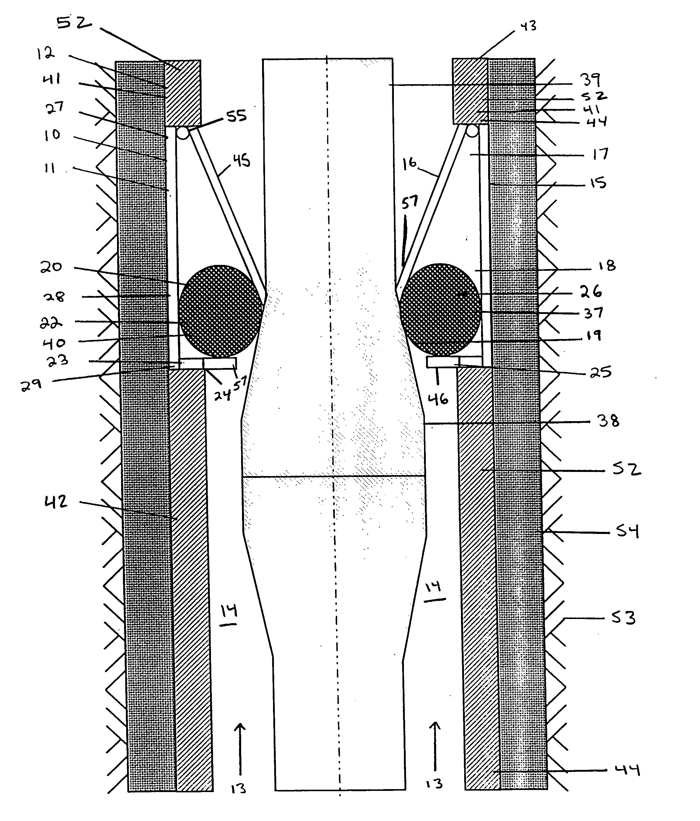
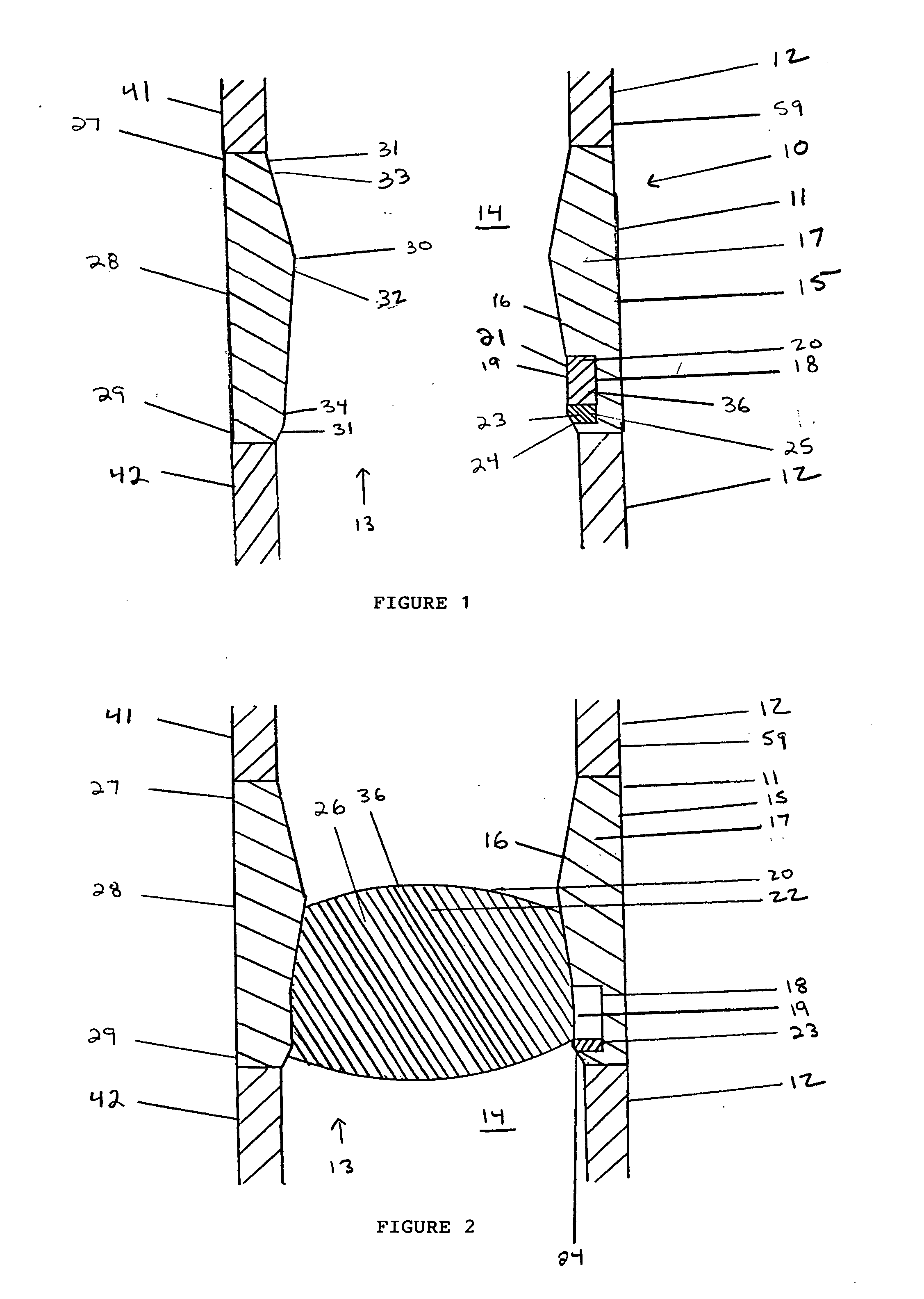
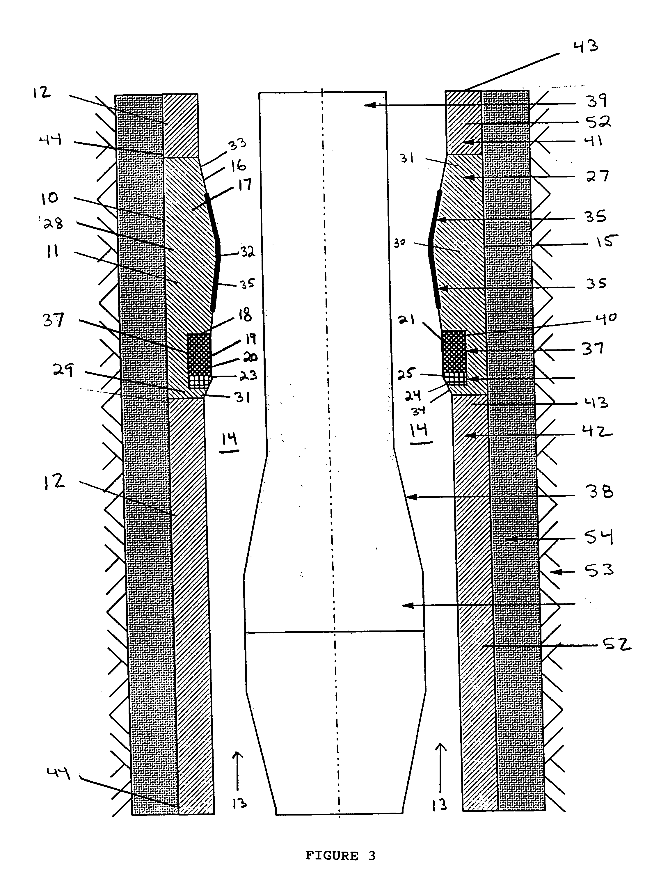
[0032] With reference to the figures where like elements have been given like numerical designation to facilitate an understanding of the present invention, and particularly with reference to the embodiment of the inflatable sealing assembly of the present invention illustrated in FIG. 1, the inflatable sealing assembly 10 may be constructed with housing 11. Housing 11 preferably is capable of being integrated with tubular 12 to permit an unobstructed flow of media 13 through flow bore 14 in tubular 12. Housing 11 may be made of any structurally rigid material. Preferably, housing 11 is constructed of steel.

[0033] Media 13 may be a variety of different materials such as fluid (water, oil, acids, and the like) or compressible media (natural gas, nitrogen, and the like) or slurries with particles (drilling fluid, ore slurry, and the like).

[0034] As shown in FIG. 1, housing 11 may include outer wall 15, inner wall 16, and interior 17 between outer and inner walls 15, 16. Preferably, ...


PUM


Abstract

An inflatable sealing assembly integrated with a flow carrier which seals the inside of the flow carrier upon detection of a physical condition (e.g. fluid pressure). The inflatable sealing assembly includes a housing, a compartment in the interior of the housing for storing an inflatable sealing device, an inflating mechanism, and a sensor. Upon detection of the physical condition in the exterior and / or interior of the flow carrier, the sensor activates the inflating mechanism, preferably automatically, to inflate and deploy the inflatable sealing device which seals off the inside of the flow carrier. The inflatable sealing device may be an air bag.

Description

FIELD OF THE INVENTION [0001] The present invention relates to an inflatable sealing assembly for sealing off an inside of a flow carrier and more particularly to an inflatable sealing assembly for sealing a flow bore in a tubular which is capable of being integrated with the tubular and which preferably seals the flow bore automatically in response to the detection of a physical condition affecting the tubular. The present invention also relates to a method of sealing off an inside of a flow carrier by inflating and deploying an inflatable sealing device. BACKGROUND OF THE INVENTION [0002] A flow carrier may be any structure through which media may be transported. The flow carrier may have a cross-section area that is shaped in a variety of configurations such as circular, square, rectangular, splined, or uneven. The flow carrier may be a tubular. A tubular may be any tube through which material is transported. A tubular may be comprised of a single tube or a series of tubes connec...

Claims


Application Information

Patent Timeline
Patent Type & Authority Applications(United States)
IPC IPC(8): E21B33/12E21B33/127E21B34/06E21B34/08
CPCE21B33/12E21B34/08E21B34/06E21B33/1277
Inventor GYNZ-REKOWSKI, GUNTHER VON
Owner ASHMIN L C
Why Eureka
Try Eureka