

Pet bottle coupler
- Summary
- Abstract
- Description
- Claims
- Application Information
AI Technical Summary
Benefits of technology
Problems solved by technology
Method used
Image

Examples
Embodiment Construction
[0021] An embodiment of blocks in accordance with the invention will be described below with reference to the drawings.
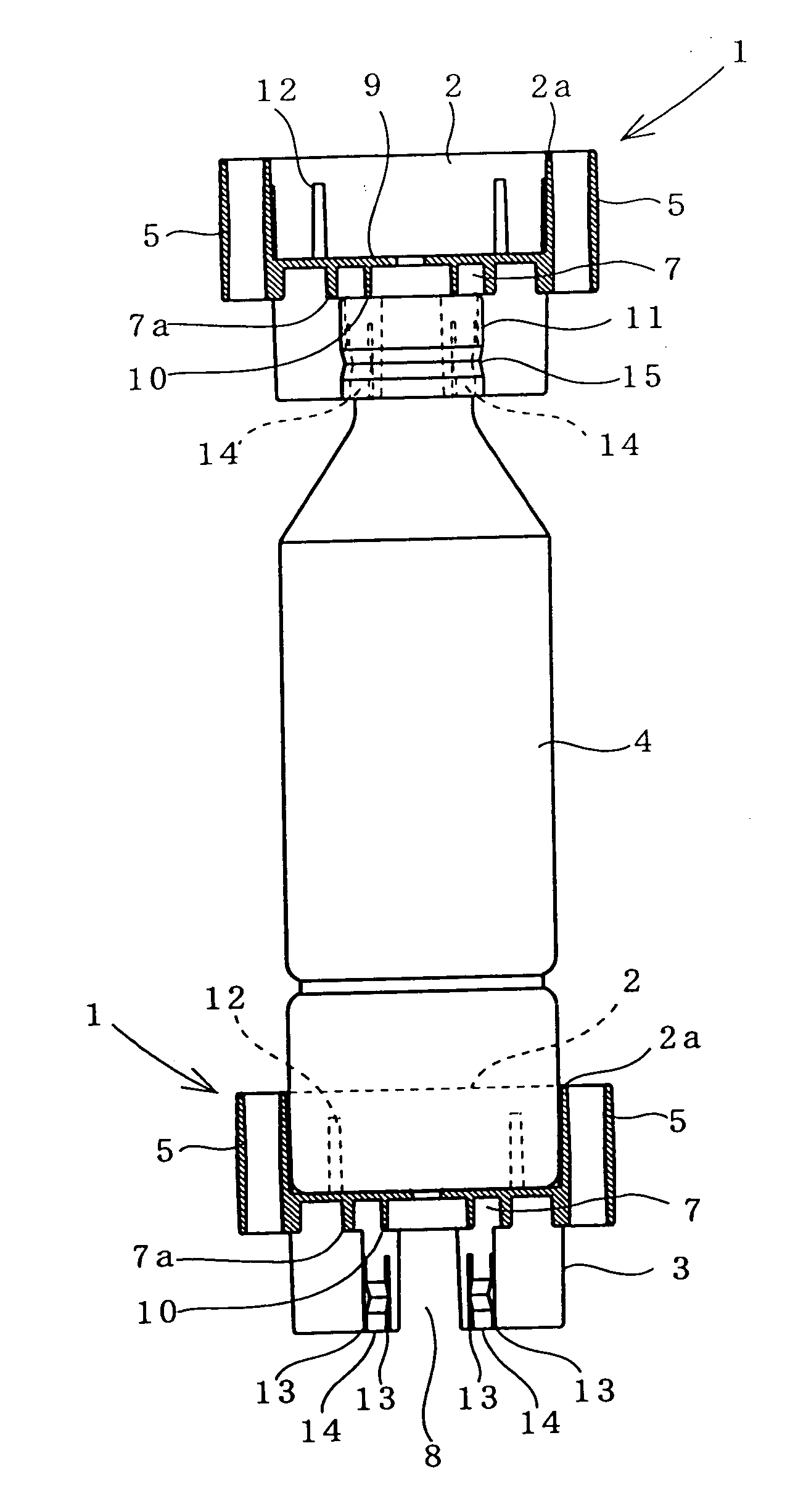
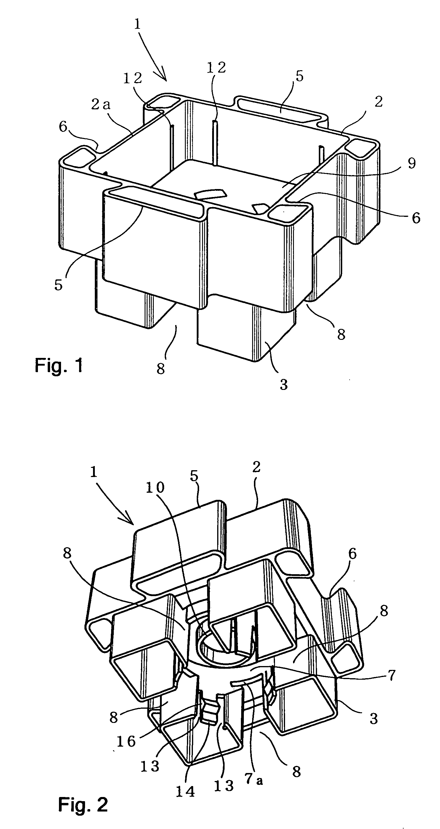
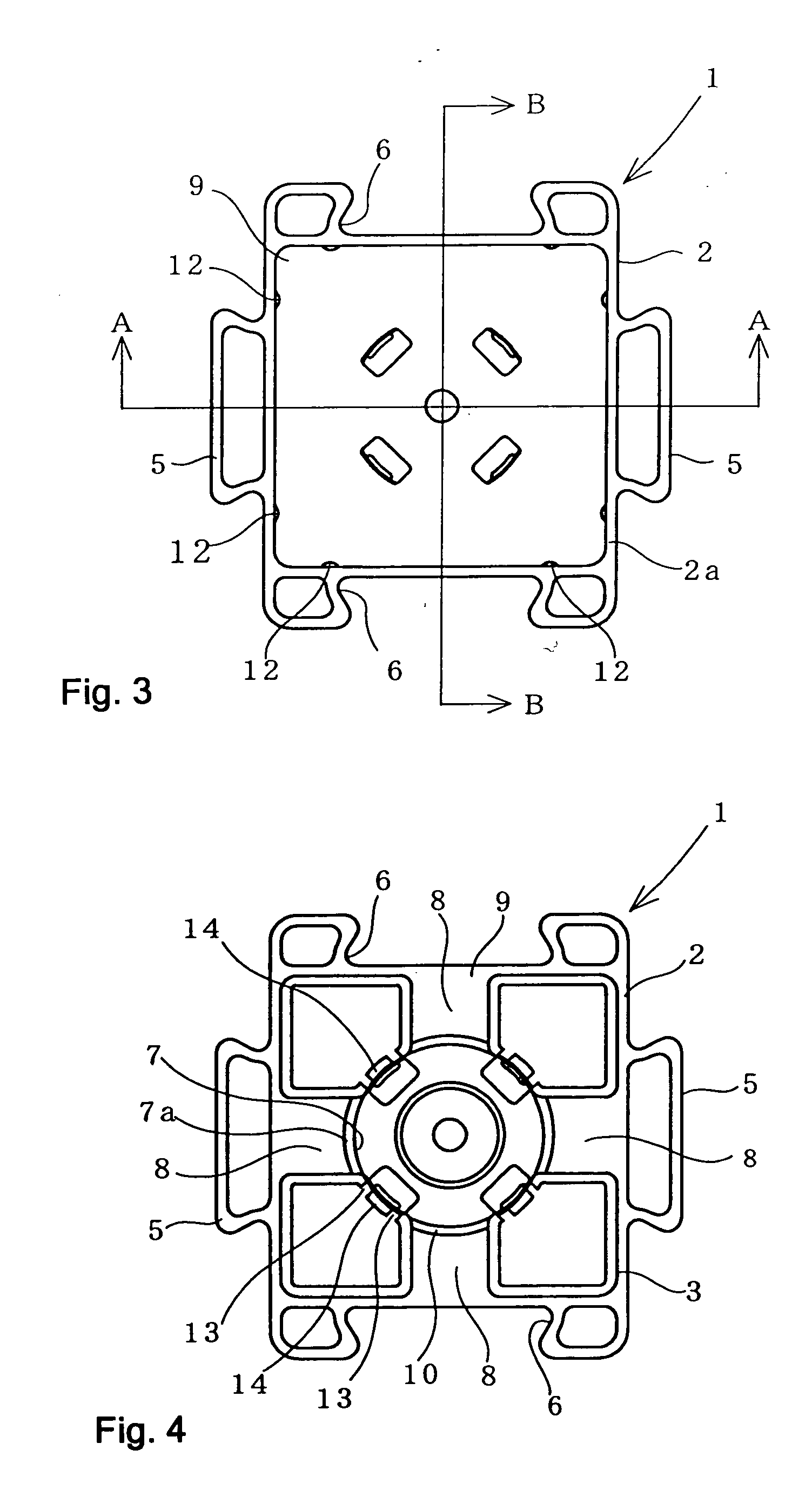
[0022] In FIGS. 1 to 6, reference numeral 1 represents the block of the invention. The block 1 includes an upper frame portion 2 and a lower leg portion 3 that are integrally formed under the condition that the leg portion 3 can be fitted to and removed from the frame portion 2. The frame portion 2 can be fitted to the lower portion of a PET bottle 4 shown in FIG. 10. The frame portion 2 includes a periphery at which coupling means 5 and 6 that couple together adjacent blocks 1 are disposed. A receiving hole 7, into which the upper portion of the PET bottle 4 can be fitted and from which it can be removed, is disposed in a center portion of the leg portions 3. Gaps 8, into which corresponding peripheral walls 2a of the frame portions 2 coupled by the coupling means are fitted, are disposed at an outer side of the receiving hole 7. The leg portion 3 is formed by mol...
PUM
| Property | Measurement | Unit |
|---|---|---|
| Size | aaaaa | aaaaa |
| Deformation enthalpy | aaaaa | aaaaa |
| Perimeter | aaaaa | aaaaa |
Abstract
Description
Claims
Application Information