

Aerial cable placing machine
a technology of aerial cable and placing machine, which is applied in the direction of cable laying apparatus, special-purpose vessels, transportation and packaging, etc., can solve the problems of many available aerial cable placing machine, outdated, and not reflecting the present needs,
Inactive Publication Date: 2005-09-01
GEN MACHINE PRODS
View PDF6 Cites 14 Cited by
- Summary
- Abstract
- Description
- Claims
- Application Information
AI Technical Summary
Problems solved by technology
Many available aerial cable placing machines are outdated and do not reflect the present needs of cable stringing applications, such as cable TV and telecommunication applications.
Such machines are not designed from the ground up for use as a cable stringing machine, and, therefore, suffer from various deficiencies.
Method used
View moreImage
Smart ImageViewing Examples

Examples
example
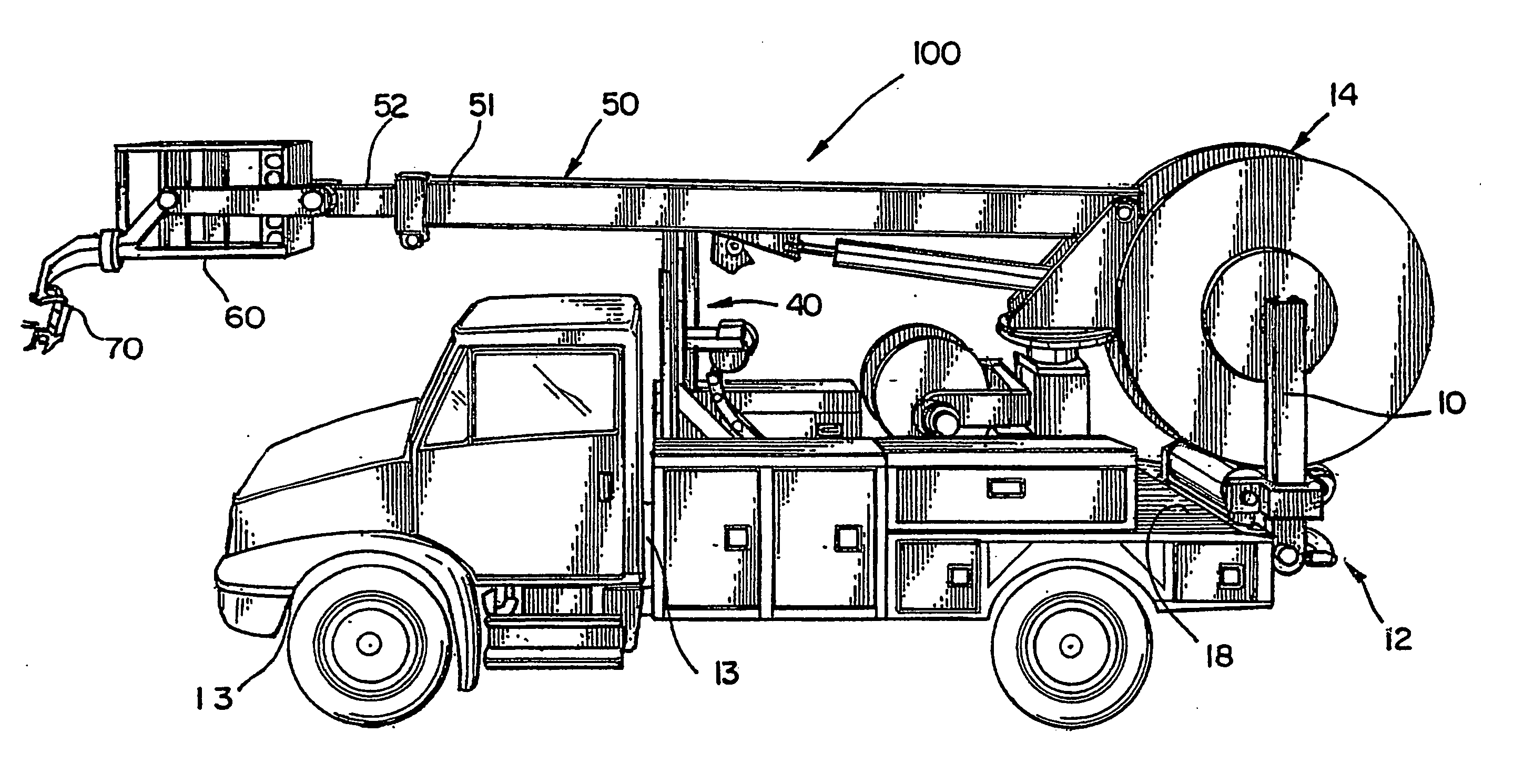
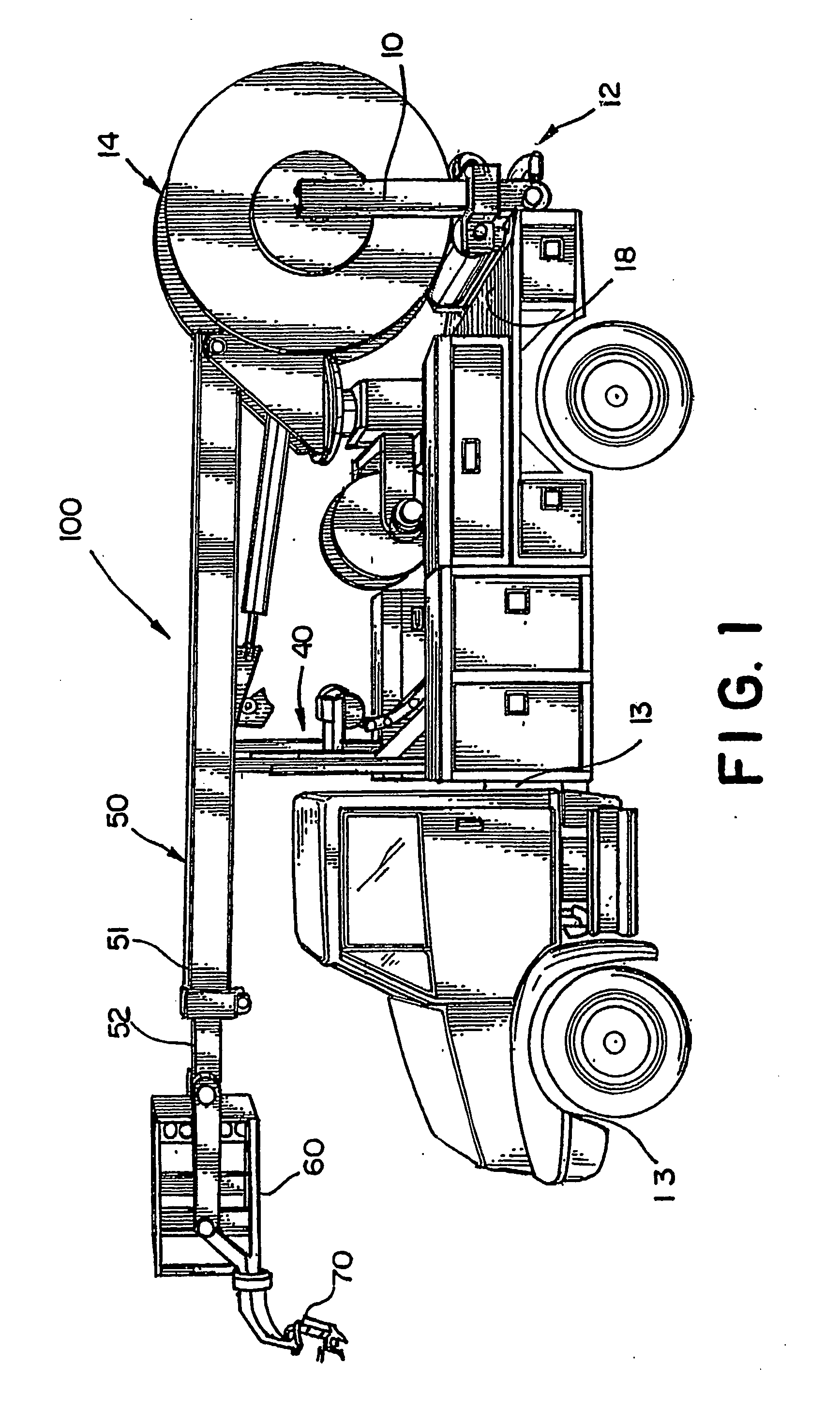
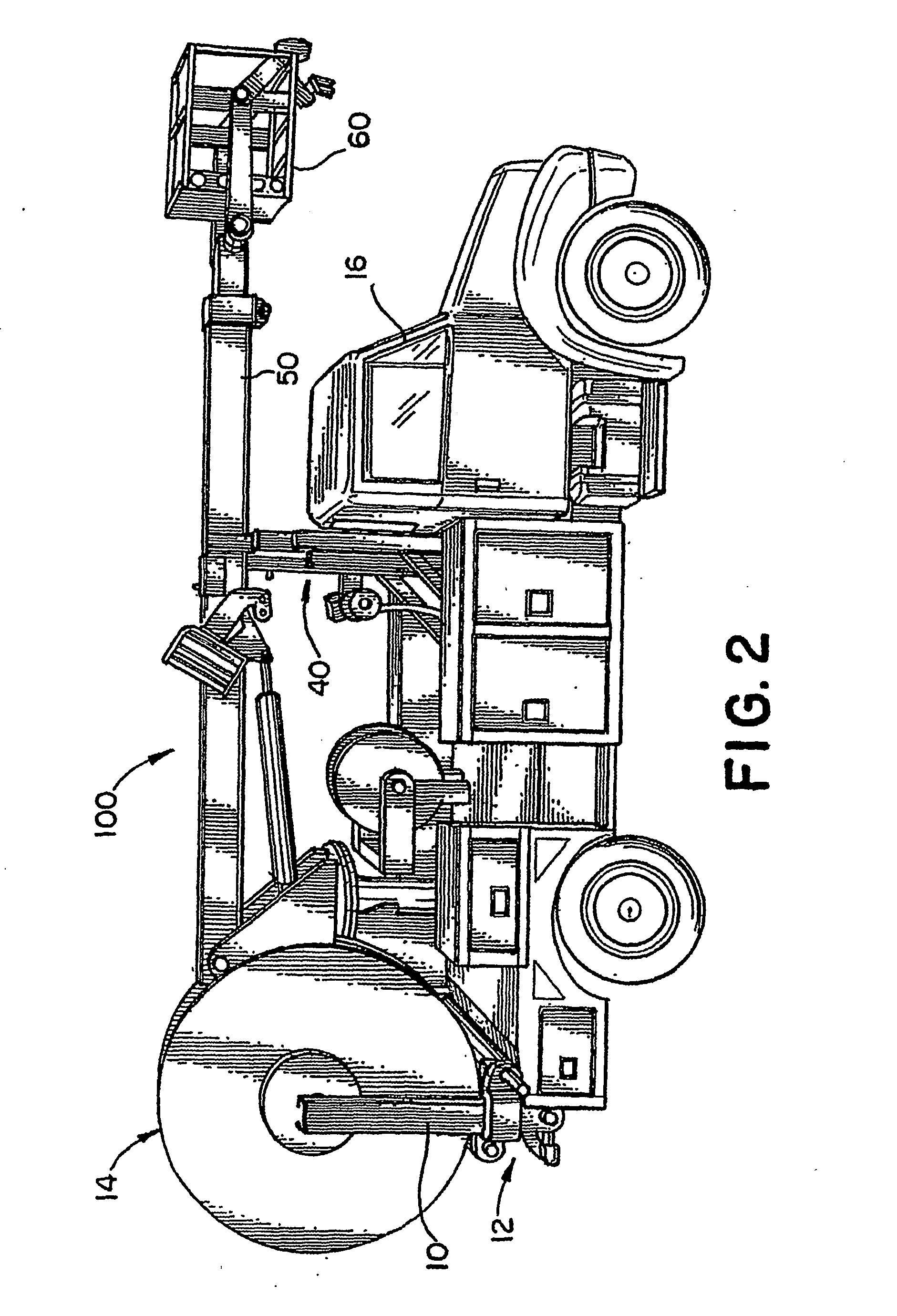
[0020]FIGS. 1-13 illustrate a wooden 3 / 32″ scale model of one conceptual configuration of a truck in accordance with the present invention. Hence, there are some deviations, omissions, and liberties taken with the scale where the detail cannot be supported by the scale or materials used. Even with the deviations, the model represents several basics concepts of the invention with the following overall specifications, features and benefits: [0021] Platform Height=37′10″[0022] Side Reach=30′[0023] Reel Loader=6000#, 84″ diameter reel (stows vertically) Self Locking reel loader mechanism [0024] Maximum Travel Height=12′[0025] 30″×30″×42″ Basket [0026] 32″ diameter upper and lower bullwheel assembly (each—110 degree radius)
Login to View More PUM
 Abstract
An aerial cable placing truck is provided. The truck includes a stringing apparatus which includes a full castoring bullwheel system for positioning a cable. The stringing apparatus pivots from side to side for placing cable on either side of the truck. The truck also includes a cantilevered turret for supporting a boom. The cantilevered turret is positioned to provide an open deck cable route along the truck deck for the cable so that the cable may taken off the truck without cutting the cable from the cable reel. A live fairlead may also be included to provide an indication of fairlead load separate from basket load.
Description
FIELD OF THE INVENTION [0001] The present invention relates generally to an aerial cable placing machine and in particular but not exclusively to a truck for placing aerial cable. BACKGROUND OF THE INVENTION [0002] Many available aerial cable placing machines are outdated and do not reflect the present needs of cable stringing applications, such as cable TV and telecommunication applications. Moreover existing machines may merely be modifications of machines originally intended for other purposes, such as a converted digger derrick boom, for example. Such machines are not designed from the ground up for use as a cable stringing machine, and, therefore, suffer from various deficiencies. For example, the weight, stability, stringing apparatus, reel loading, reel driving capabilities, load monitoring, component design and ergonomics are areas in which major improvements can be made. In sum, a need exists in the market for an aerial cable placing machine that is well thought out and is ...
Claims
Login to View More Application Information
Patent Timeline
 Patent Type & AuthorityApplications(United States)
IPC IPC(8): H02G1/04H02G1/06
CPCH02G1/04
InventorYOUNG, ROBERT A.
OwnerGEN MACHINE PRODS