Modular control system for an AC motor

a control system and ac motor technology, applied in the direction of electrical apparatus construction details, dynamo-electric converter control, multiple dynamo-motor starters, etc., can solve the problems of communication and control loss, large control system, complicated device, etc., and achieve the effect of simple and easy installation

Inactive Publication Date: 2005-09-01
EATON CORP
View PDF6 Cites 39 Cited by
  • Summary
  • Abstract
  • Description
  • Claims
  • Application Information

AI Technical Summary

Benefits of technology

[0006] Therefore, it is a primary object and feature of the present invention to provide a modular control system for an AC motor that may be simply and easily installed in various environments.
[0032] As described, it can be appreciated that modular control system 10 of the present invention allows for a user to simply and easily interconnect control system 10 to a power source and to AC motor 26 in various environments. Further, supplemental power supply 42 allows for the control circuit 20 to be programmed without the presence of incoming electrical power on lines L1-L3. This facilitates the initial set up of modular control system 10 on site, or alternatively, allows for the programming of control circuit 20 prior to installation at the site without regard to the presence of electrical power at such site. This, in turn, makes modular control system 10 easier and quicker for contractors to install. It can be further understood that other types of peripheral devices for use in the control of power incoming to and outgoing from control system 10, as well as, additional components for controlling operation of motor 26 may be housed in intermediate module 14 without deviating from the scope of the present invention.

Problems solved by technology

Typically, these drive systems are large, complicated devices that incorporate a drive unit and a bypass unit in a single enclosure.
However, while most prior bypass units are designed for redundancy, the redundancy of these prior bypass units is limited.
By way of example, for electronic based bypass units, communication and controls are lost when the incoming utility power to the AC drive system is lost.
In addition, due to the complicated nature of present AC drive systems, large amounts of engineering time may be required to incorporate these AC drive systems into new or different applications and environments.
For the user, a complicated AC drive system translates into complicated set up procedures.
For example, due to the complexity and large footprint of these prior AC drive systems, it may be difficult to interconnect such AC drive systems in certain environments since all of the structural components of these prior AC drive systems are arranged in a single enclosure.
While functional in certain applications, the AC drive system disclosed in the '069 patent is limited.
This, in turn, may complicate the installation procedure.
Further, installation in the field of a bypass unit for a previously installed AC drive unit often requires remounting of the AC drive unit thereby increasing the overall cost to an end user.
It can be appreciated that the use of separate power and bypass units increases the overall footprint of the AC drive system, making such a system difficult or uneconomical to install in various environments.

Method used


Image

  • Modular control system for an AC motor
  • Modular control system for an AC motor
  • Modular control system for an AC motor

Examples


Embodiment Construction

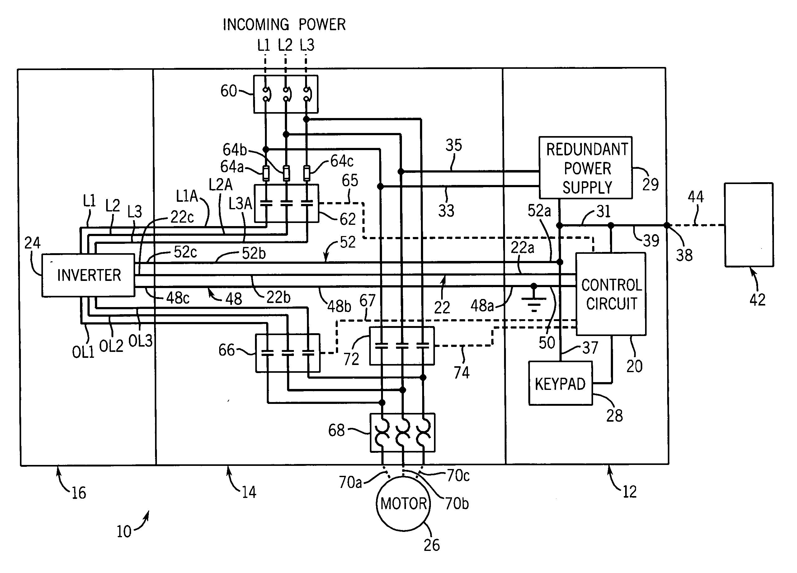
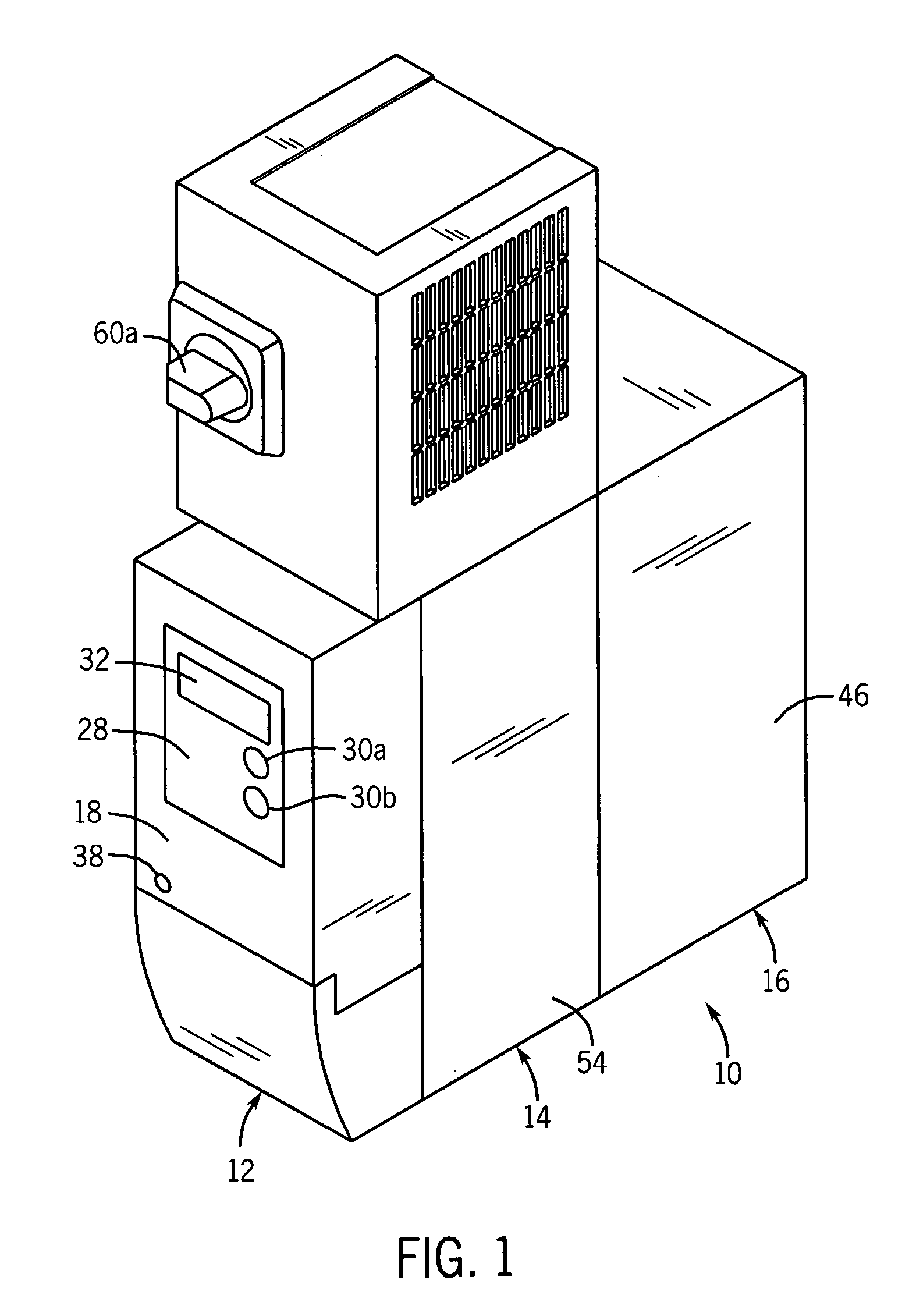
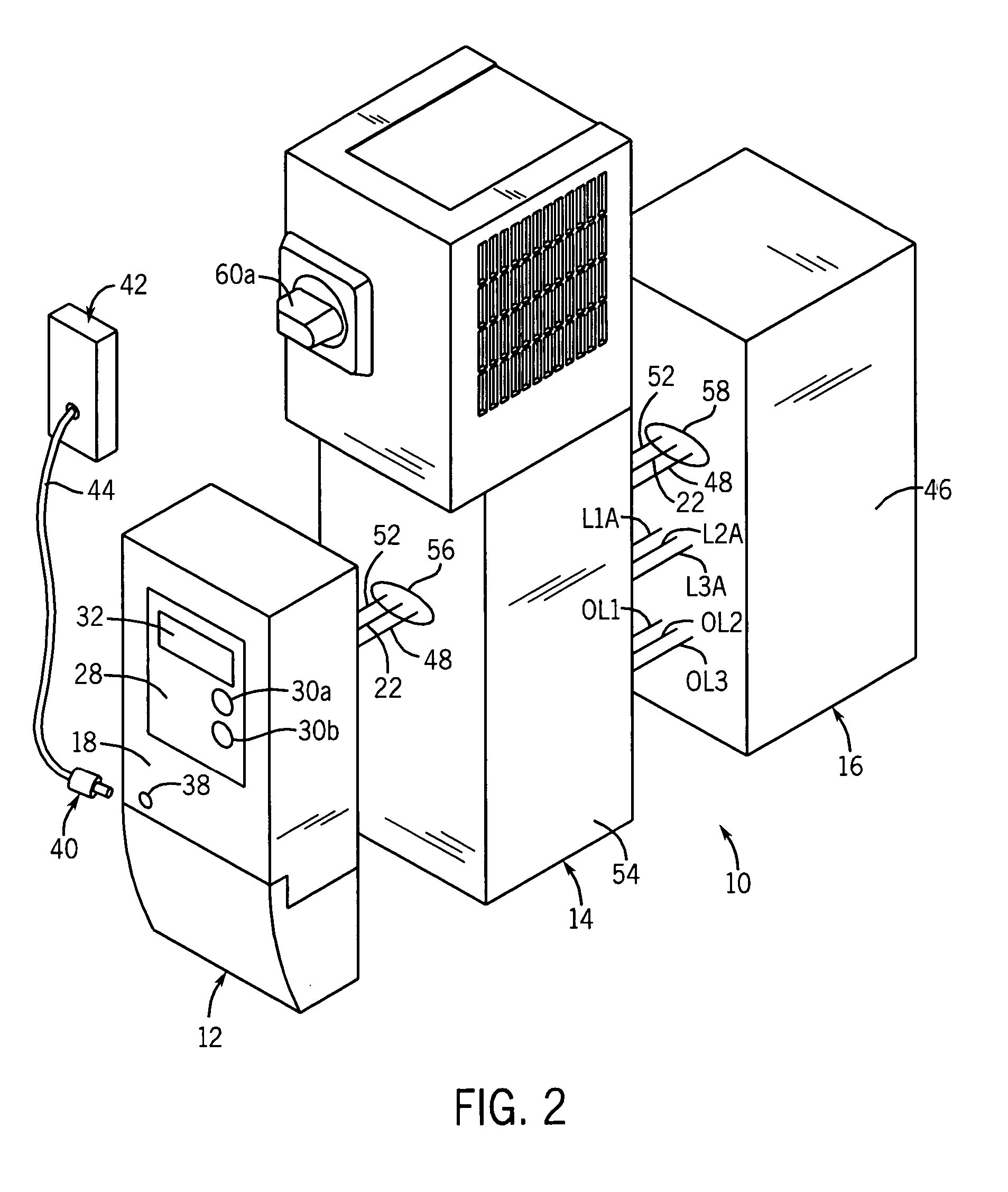
[0023] Referring to FIGS. 1-3, a modular control system in accordance with the present invention is generally designated by the reference numeral 10. Control system 10 includes interface module 12, intermediate module 14 and drive module 16 physically connected in any suitable manner such as by screws or the like. It can be appreciated that additional modules may be positioned between the interface module 12 and drive module 16 without deviating from the scope of the present invention.

[0024] Interface module 12 includes housing 18 that receives control circuit 20 therein. Control circuit 20 incorporates a central processing unit (CPU) that generates switching signals on lines 22 for inverter 24. As is conventional, inverter 24 converts three-phase, 60 hertz input power to an adjustable frequency and voltage source for controlling the speed of AC motor 26. The switching signals provided by the CPU of control circuit 20 adjust the voltage and the frequency of the energization signals...


PUM


Abstract

A modular control system for an AC motor is provided. The modular control system includes a drive module, a control module, and an intermediate module therebetween. The drive module houses an AC drive that interconnects an AC motor to a utility power source. Control structure for controlling operation of the AC drive is provided in the control module. The control structure and the control module and AC drive in the drive module are electrically coupled through the intermediate module.

Description

FIELD OF THE INVENTION [0001] This invention relates generally to drives for controlling operation of AC motors, and in particular, to a modular control system incorporating a drive to control operation of an AC motor. BACKGROUND AND SUMMARY OF THE INVENTION [0002] As is known, conventional AC drive systems convert three-phase, 60 hertz input power to an adjustable frequency and voltage source for controlling the speed of an AC motor. Typically, these drive systems are large, complicated devices that incorporate a drive unit and a bypass unit in a single enclosure. The bypass unit is provided in order to maintain electrical power to the AC motor in the event that the drive unit fails. However, while most prior bypass units are designed for redundancy, the redundancy of these prior bypass units is limited. By way of example, for electronic based bypass units, communication and controls are lost when the incoming utility power to the AC drive system is lost. Consequently, it can be ap...

Claims


Application Information

Patent Timeline
IPC IPC(8): H02M7/00H02P1/54
CPCH02M7/003H05K7/1432H05K5/0021H05K7/14327
Inventor WIRTZ, JOHN M.SIEBENLIST, PAUL J.ARMES, JAMES E.SCHNUR, RICK E.
Owner EATON CORP
Why Eureka
Try Eureka