Method and apparatus for machining a blank from all directions

Inactive Publication Date: 2005-09-01
GENERAL ELECTRIC TECH GMBH
View PDF11 Cites 7 Cited by
  • Summary
  • Abstract
  • Description
  • Claims
  • Application Information

AI Technical Summary

Benefits of technology

[0015] A particular embodiment of the method according to the invention works in such a way that the blank is first of all shaped on its one side in the first machining step and is then shaped on its other side in the second machining step. That is to say the first adapter grips the blank at a first end, in the first machining step the second end of the blank is given its final partial shape corresponding to the intended use, the second adapter then grips the partly machined blank at the partial shape and, in the second machining step, the first end is processed into the final overall shape. If the final overall shape involves a turbine blade, the root region is preferably processed in the first machining step, then this root region is used for the mounting for the second machining step, and the tip region is processed in the second machining step. The opposite process can also be realized, in particular in the case of a turbine blade with a shroud band; that is to say that the tip region with shroud band is processed in the first step. In addition, it proves to be advantage

Problems solved by technology

Normally, it has always been assumed that the forces produced during the machining lead either to damage to t

Method used


Image

  • Method and apparatus for machining a blank from all directions
  • Method and apparatus for machining a blank from all directions
  • Method and apparatus for machining a blank from all directions

Examples


Example

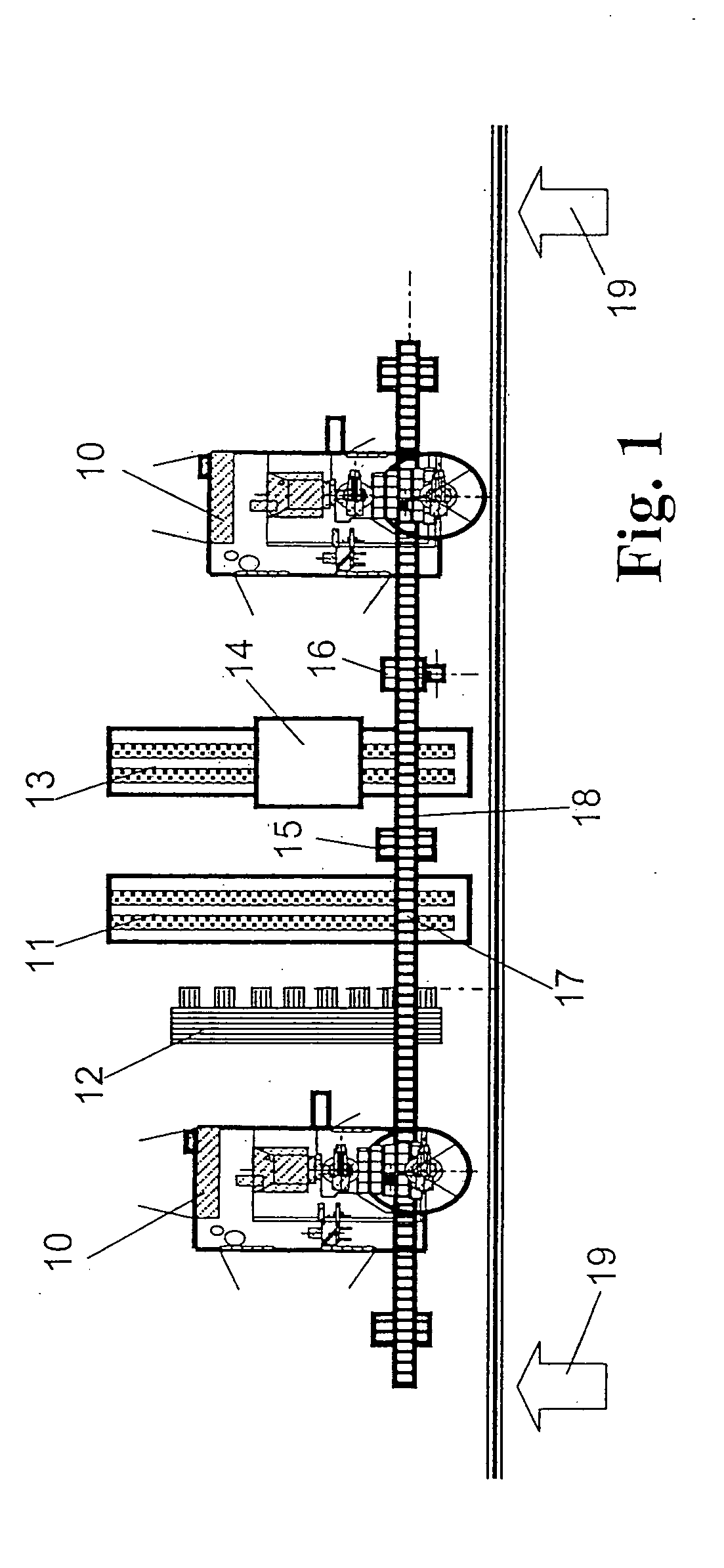
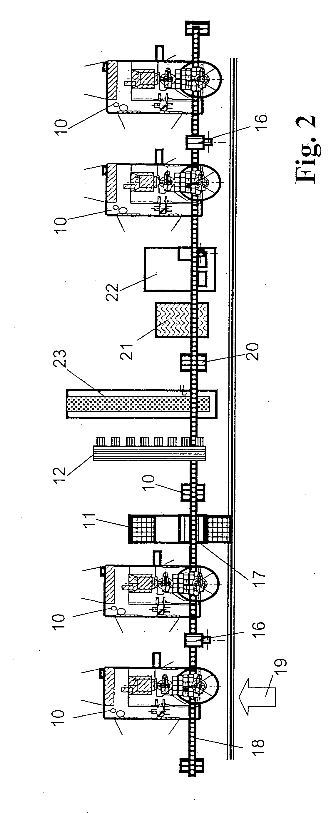
[0047] First of all, possible layouts of cells for the machining according to the invention of workpieces are to be shown and explained with reference to FIGS. 1 to 3, then the actual process sequences of the two essential exemplary embodiments are to be shown and explained with reference to FIGS. 4 and 5.

[0048]FIG. 1 shows the layout of a cell from above for carrying out the process according to the invention. This is a small cell having two blade milling machines 10 which are loaded with the workpieces to be machined and are respectively unloaded via a handling portal 18. To this end, the handling portal 18 has a handling system with a gripper 16. If appropriate, a plurality of such handling systems 16 can be mounted on the same handling portal 18 in a traversable manner. The handling portal 18, via further units essentially remote from a working front 19, is supplied with blanks by means of a loading belt 11 in the form of a paternoster. The blanks are gripped by the gripper of ...


PUM

PropertyMeasurementUnit
Weightaaaaaaaaaa
Lengthaaaaaaaaaa
Lengthaaaaaaaaaa

Abstract

In a method of machining a blank from all directions using at least one machine tool, such as a milling machine, production of the ready-to-use, measured component which is controlled and classified with regard to quality, such as a turbine blade, occurs in as few steps and setups as possible with the use of machine tools and milling machines that as far as possible are of identical design. The blank, in a first machining step, is held by at least one first adapter and a first region is given its final partial shape corresponding to the intended use by a machine tool or milling machine. In a second machining step, the partly machined blank is held by at least one second adapter in the first, finally machined region, and the remaining region is given its final overall shape corresponding to the intended use by a machine tool or milling machine.

Description

CROSS-REFERENCE TO RELATED APPLICATIONS [0001] This application is a continuation of the U.S. National Stage designation of co-pending International Patent Application PCT / CH03 / 00052 filed Jan. 23, 2003, the entire content of which is expressly incorporated herein by reference thereto. FIELD OF THE INVENTION [0002] The present invention relates to a method of machining blanks or pre-machined workpieces from all directions using at least one machine tool, such as a milling machine for example, in order to produce ready-to-deliver components which are finally machined in their three-dimensional shape. BACKGROUND OF THE INVENTION [0003] During the production of turbine blades, work is normally carried out with multi-spindle machining. This means that a blank is first of all subjected to rough pre-machining, then the airfoil region is processed in detail, and then the tip and finally the root are produced. Between these individual machining steps, the workpiece must be reset in each cas...

Claims


Application Information

Patent Timeline
IPC IPC(8): B23Q11/00B23C3/00B23C3/18B23Q3/06B23Q7/04B23Q39/04
CPCB23B2215/81B23C3/18B23C2215/44B23Q7/047B23Q39/048B23Q2230/008Y10T29/49316Y10T409/303136Y10T409/309016Y10T409/303808Y10T409/307448Y10T29/49336Y10T409/303864Y10T29/49996
Inventor KILLER, FRANZSCHERER, JOSEF
Owner GENERAL ELECTRIC TECH GMBH
Why Eureka
Try Eureka