Turbine blade shroud cutter tip

a turbine blade and cutter tip technology, applied in the direction of liquid fuel engines, marine propulsion, vessel construction, etc., can solve the problems of increased load and stress on the turbine blade, increased vibration and damping of the blade, and the shroud exhibits a bending moment at the interface region, so as to reduce the bending moment, reduce the bending stress of the shroud, and reduce the bending stress

Active Publication Date: 2005-09-01
ANSALDO ENERGIA SWITZERLAND AG
View PDF7 Cites 29 Cited by
  • Summary
  • Abstract
  • Description
  • Claims
  • Application Information

AI Technical Summary

Benefits of technology

[0006] The tooth, which in prior art shroud designs, has been known to be a significant factor in shroud bending stresses, is repositioned to reduce its bending moment on the airfoil to shroud region and associated shroud bending stresses. It has been determined that the tooth can be repositioned without compromising cutting performance, while at the same time reducing shroud

Problems solved by technology

As turbine blade length increases, the blades become more susceptible to vibration and require dampening.
While this sealing and dampening design is effective, the use of a shroud causes additional load and stress on the turbine blade due to its shape, weight, and position.
Furthermore, the shroud exhibits a bending moment at the interface region between the shroud and airfoil due to the large mass canti

Method used


Image

  • Turbine blade shroud cutter tip
  • Turbine blade shroud cutter tip
  • Turbine blade shroud cutter tip

Examples


Embodiment Construction

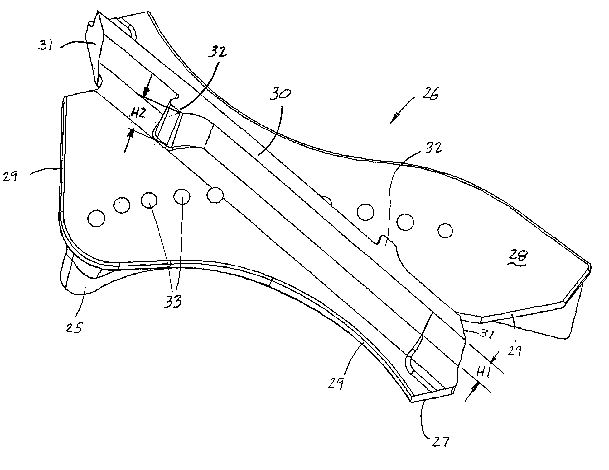
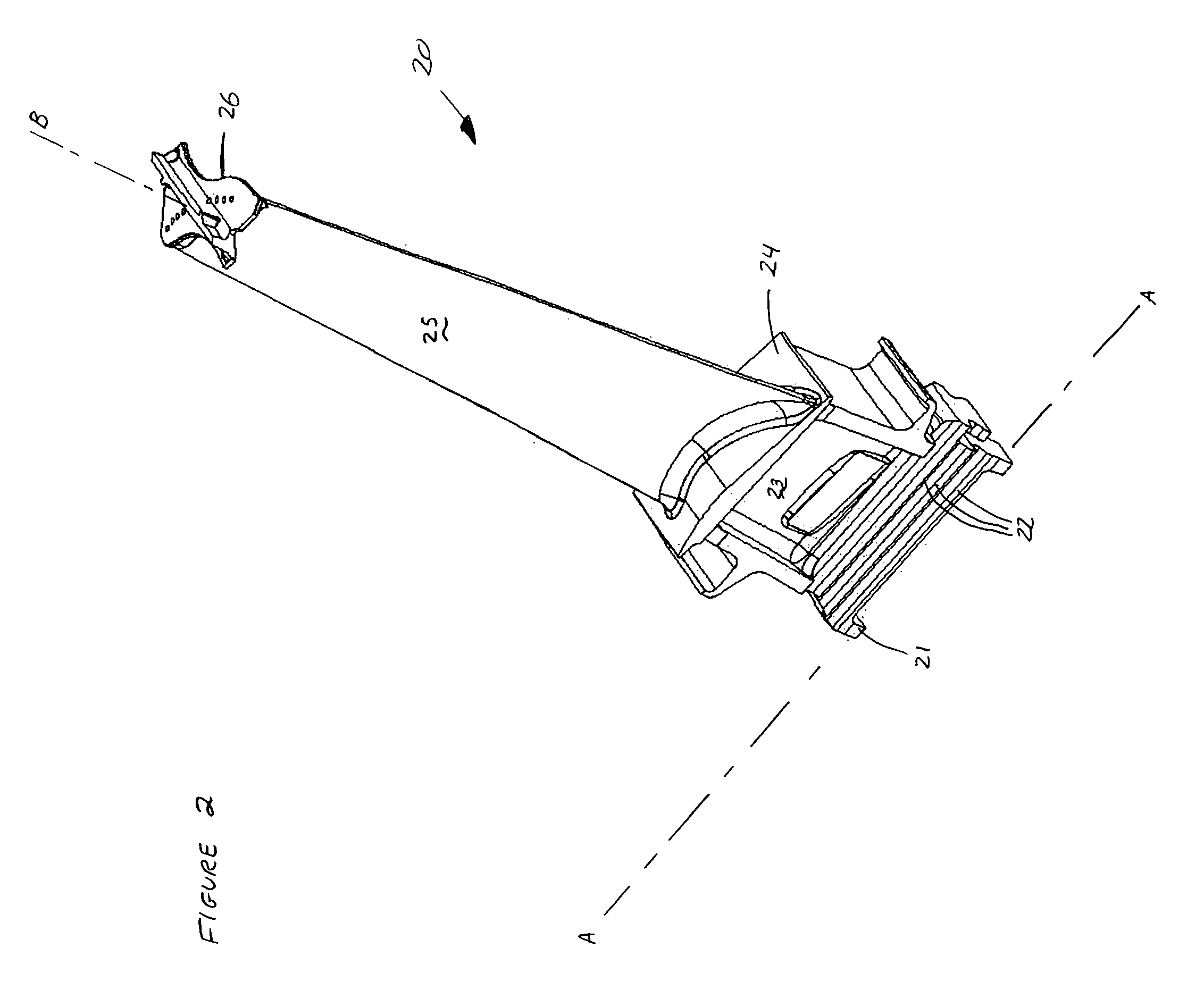
[0015] Referring to FIG. 2, a turbine blade 20 incorporating the present invention is shown. Turbine blade 20 comprises an attachment 21 that extends generally parallel to an axis A-A and has a plurality of serrations 22 for attaching turbine blade 20 to a blade disk (not shown). In the preferred embodiment, serrations 22 are generally parallel to axis A-A. Extending radially outward from attachment 21 is a region 23 commonly referred to as a blade neck. Neck 23 connects to platform 24, which is generally planar in shape. Extending radially outward from platform 24 is airfoil 25, wherein airfoil 25 also includes a generally radially extending stacking line B-B through which sections of the airfoil are stacked to create airfoil 25. Referring now to FIGS. 3 and 4, extending radially outward from airfoil 25 is shroud 26 with the shroud comprising a first surface 27 fixed to airfoil 25 at an end opposite of platform 24, a second surface 28 in spaced relation to and generally parallel to...


PUM


Abstract

A shroud for use with a turbine blade is disclosed wherein the shroud provides at least one knife edge with at least one tooth for cutting a groove in a compliant rub strip that minimizes wear on the knife edge. The tooth is positioned along the knife edge a distance substantially away from the ends of the knife edge such that the moment created by the tooth mass and its effect on shroud bending stress is significantly reduced, thereby resulting in increased turbine blade durability.

Description

TECHNICAL FIELD [0001] This invention relates to shrouded turbine blades and more specifically to an improved cutter tip design that reduces the bending stresses in the shroud to airfoil interface region of a turbine blade. BACKGROUND OF THE INVENTION [0002] Gas turbine engines have compressor and turbine blades of varying length in order to compress and expand the fluid flow passing through the engine. For the turbine section, as energy is extracted from the hot combustion gases, the fluid expands and the turbine section expands accordingly, including the stages of turbine blades. As turbine blade length increases, the blades become more susceptible to vibration and require dampening. In order to dampen the vibrations, a shroud is added to the blade, most often at the blade tip. The shroud serves to reduce blade vibrations by interlocking adjacent turbine blade tips, as well as to seal the blade tip region to prevent hot combustion gases from leaking around the blade tip and bypass...

Claims


Application Information

Patent Timeline
IPC IPC(8): B63H1/16F01D5/20F01D11/08
CPCF01D5/225F05B2240/33F01D11/08
Inventor SELESKI, RICHARD
Owner ANSALDO ENERGIA SWITZERLAND AG
Why Eureka
Try Eureka