Process flow control circuit

a flow control and circuit technology, applied in the direction of pump control, positive displacement liquid engine, non-positive displacement fluid engine, etc., can solve the problems of increased differential pressure, trouble, and drop in the amount of fluid flow transmitted through the devi

Inactive Publication Date: 2005-09-01
VINSON JAMES WOODROW JR
View PDF11 Cites 53 Cited by
  • Summary
  • Abstract
  • Description
  • Claims
  • Application Information

AI Technical Summary

Benefits of technology

[0008] The controller maintains the power of the fluid transfer device as a function of the fluid flow through the fluid transfer device and of the pressure differential measured by the pressure differential measurement device. The varying pressure drop within the fluid flow circuit can come from a rise in pressure in the fluid flow circuit within the high pressure portion of the fluid flow circuit (downstream of the fluid transfer device).
[0009] One embodiment of the fluid flow circuit of the present invention can include a pump having an inlet port and an outlet port with a first pressure measurement device disposed within the inlet port and a power monitoring device that measures the power of the pump. Also included in the alternative embodiment is a speed control device that measures the rotational speed of the pump and is capable of varying the rotational speed of the pump, a second pressure measurement device disposed within the outlet port, and a controller in communication with the first pressure measurement device, the second pressure measurement device, the power monitoring device, and the speed control device. The controller coop

Problems solved by technology

Typically an increase in differential pressure results in a drop in the amount of fluid flow transmitted through the device.
In most instances this increase in differential pressure is caused by an increase in pressure drop within the flow circuit of which the device is included.
Cases where the pressure drop within a flow circuit is caused by an increase in pressure drop across a piece of equipment can be especially troublesome when the pressure drop increase is caused by equipment fouling.
Equipment fouling usually increases over time instead of instead of stabilizing or getting cleaner—thus the pressure drop across a fouled piece of e

Method used


Image

  • Process flow control circuit
  • Process flow control circuit
  • Process flow control circuit

Examples


Embodiment Construction

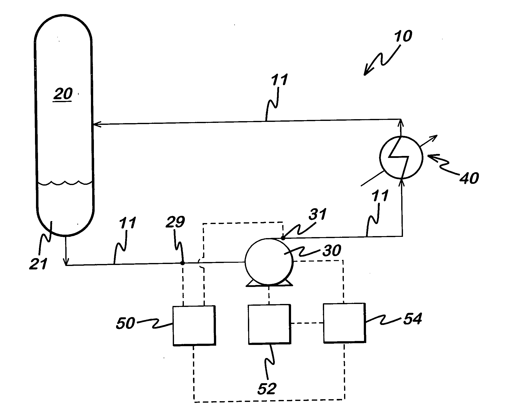
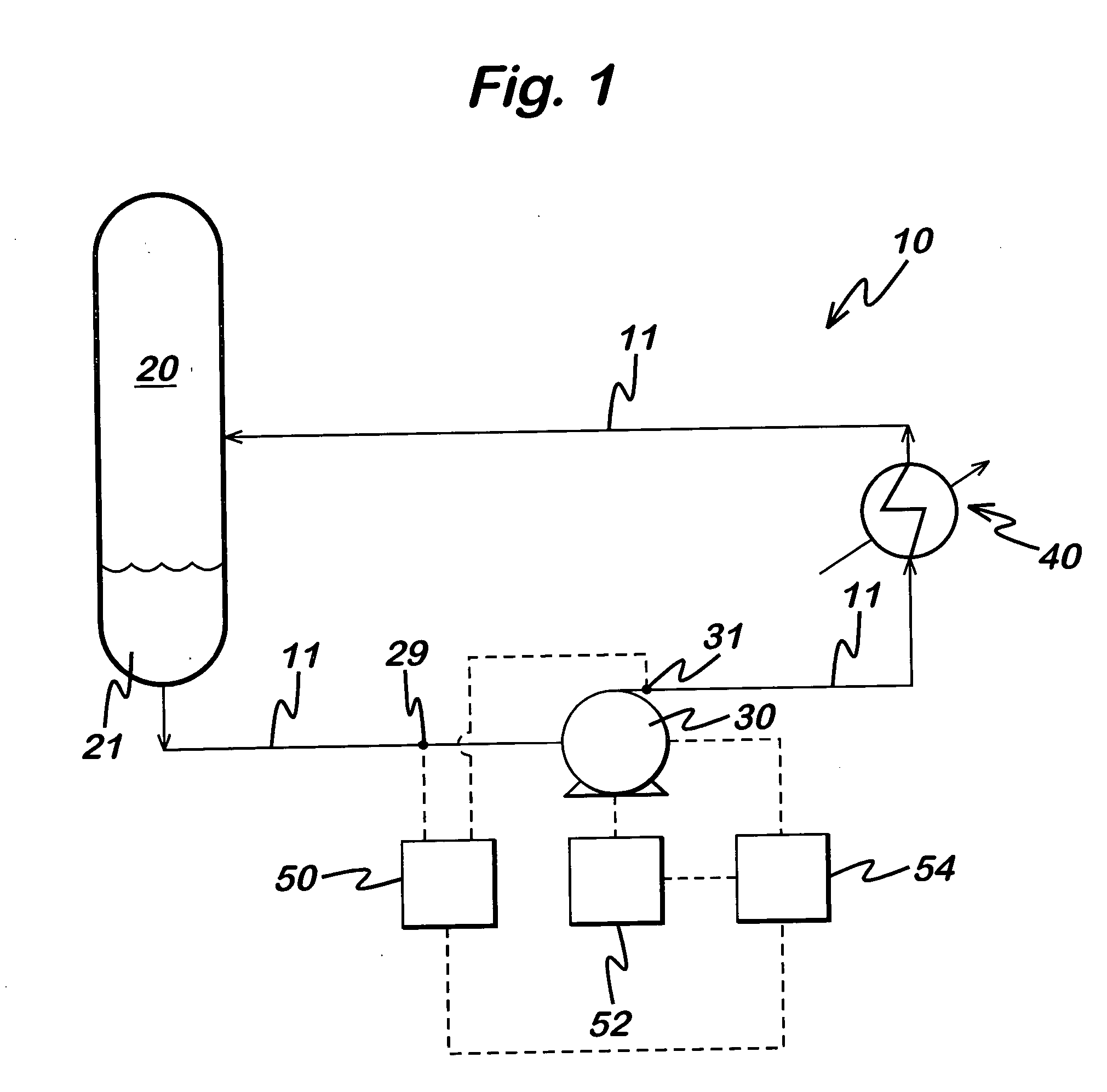
[0013] With reference to the drawing herein, a flow circuit 10 comprising, piping 11, a vessel 20, a flow transfer device 30, and a fluids processing device 40 is shown in FIG. 1. The fluids processing device 40 is shown as a heat exchanger with the process fluid of the flow circuit 10 passing through its tube side. However, any number of other process components could comprise the fluids processing device 40, such as a filter, dryer, separator, or coalescer. Likewise, these substitute elements, or other like elements, could also take the place of the vessel 20.

[0014] The specific elements of the flow circuit 10 as illustrated in FIG. 1 are not critical to the invention, but instead are shown for illustration. The present invention will operate with the specific items shown in FIG. 1, or with additional fluids handling hardware, such as other vessels, exchangers, and the like, or fewer items as shown. Similarly the fluid transfer device 30 is shown as a centrifugal pump, but could ...


PUM


Abstract

A flow control scheme for use with a flow circuit, including a fluid transfer device such as a pump or a compressor. The flow control scheme monitors the power and pressure differential of the fluid transfer device. The flow control scheme is capable of maintaining the flow of the fluid transfer device at a baseline value in response to varying operational conditions within the flow circuit.

Description

BACKGROUND OF THE INVENTION [0001] 1. Field of the Invention [0002] The invention relates generally to the field of the flow control of fluids. More specifically, the present invention relates to a method and apparatus to control flow through a fluid flow circuit in response to variations in the fluid flow circuit. [0003] 2. Description of Related Art [0004] Fluid flow circuits generally comprise multiple pieces of fluids handling hardware, such as heat exchangers, valves, vessels, drums and the like that are connected together by a series of piping to form the circuit. In many instances the motive force for driving the fluid through the circuit is provided by a fluid transfer device, such as a compressor or a pump. Generally the fluid flow through fluid transfer devices is dependent upon the pressure imparted onto the fluid by the fluid transfer device. This pressure can also be referred to as the differential pressure across the device. Typically an increase in differential pressu...

Claims


Application Information

Patent Timeline
IPC IPC(8): F04B49/00F04B49/06F04D15/00
CPCF04B2205/01F04D15/0066F04B2205/09F04B2205/05
Inventor VINSON, JAMES WOODROW JR.
Owner VINSON JAMES WOODROW JR
Why Eureka
Try Eureka