Electric motor brush assembly

a brush assembly and electric motor technology, applied in the direction of current collectors, dynamo-electric machines, coupling device connections, etc., can solve problems such as potential damage to the field case housing

Inactive Publication Date: 2005-09-01
BLACK & DECKER INC
View PDF52 Cites 11 Cited by
  • Summary
  • Abstract
  • Description
  • Claims
  • Application Information

AI Technical Summary

Benefits of technology

[0007] In accordance with one aspect of the present invention, an electric motor brush assembly with an electrically conductive brush box adapted to hold a brush and having at least one crimping tab is provided. A base member is formed of high temperature resistant plastic and is adapted to cooperate with the crimping tab to retain the brush box against a surface of th

Problems solved by technology

As such, the temperature of the brush box can be suf

Method used


Image

  • Electric motor brush assembly
  • Electric motor brush assembly
  • Electric motor brush assembly

Examples


Embodiment Construction

[0022] The following description of the preferred embodiment(s) is merely exemplary in nature and is in no way intended to limit the invention, its application, or uses. For example, although the motor is illustrated and discussed herein in terms of its use in association with a power tool, the motor may also be used for various other applications.

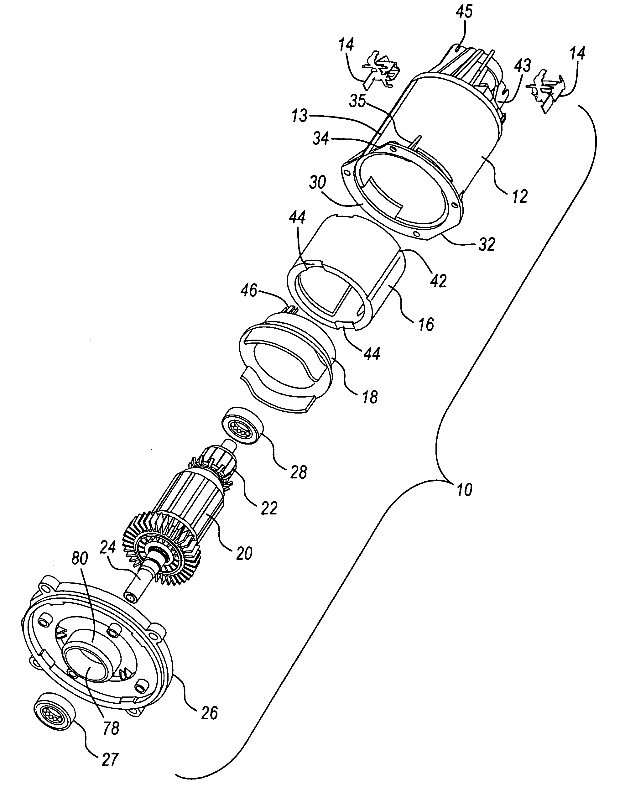
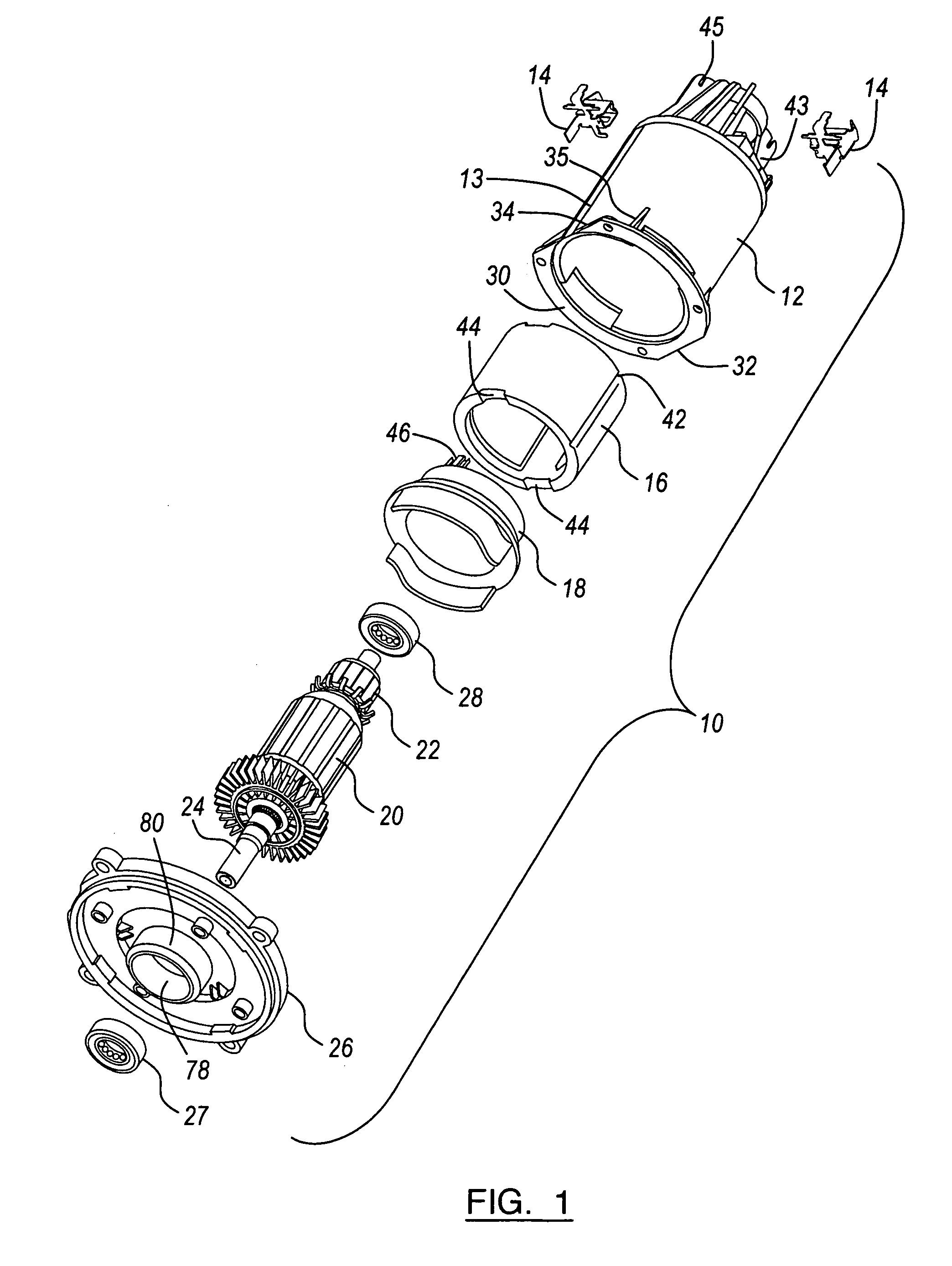
[0023] Referring to FIG. 1, a preferred embodiment of a motor 10 according to the present invention is illustrated. Motor 10 includes a field case housing 12, brush assemblies 14, motor can 16, baffle 18, armature 20, commutator 22, shaft 24, end plate 26 and front 27 and rear 28 bearings. Housing 12 is preferably molded as a single, integral part and includes a generally cylindrical flange 30. Flange 30, however, includes a shorter, elongated, linear, straight edge 32 (or short flat spot) and a longer, elongated, linear, straight edge 34 (or long flat spot).

[0024] Referring to FIG. 1 and FIG. 2, field case housing 12 is a generally tubu...


PUM


Abstract

An electrically conductive brush box is located against the upper surface of a base and has crimping tabs located against an oppositely disposed crimping surface. The base is formed of high temperature resistant plastic. A field case housing has a seat with a retention member adapted to retain the base against the seat. A screw is threaded into the field case housing such that the head presses against a surface of the base member to retain the base member in the seat. The screw member is located in non-contacting relationship with the electrically conductive brush box. A spacer member is adapted to space the portion of the crimping tab against the crimping surface away from the field case housing. The brush box includes a biasing member holder and the crimping tabs are located adjacent the holder.

Description

CROSS-REFERENCE TO RELATED APPLICATIONS [0001] This application is a Continuation of International Application No. PCT / US03 / 33572, filed Oct. 22, 2003 and designating the United States. This application claims the benefit of U.S. application Ser. No. 10 / 286,111, filed on Oct. 31, 2002, now U.S. Pat. No. 6,798,109, issued Sep. 28, 2004. The disclosures of the above applications are incorporated herein by reference.FIELD OF THE INVENTION [0002] The present invention relates to electric motors; and more particularly, to the brush assembly of electric motors. BACKGROUND OF THE INVENTION [0003] Electric motors are used in a variety of applications, including power tools. Such electric motors typically include a motor shaft, a motor armature, magnets, a fan baffle, a commutator assembly, brushes and electrical leads. The electrical leads selectively link brushes to a power source. The motor armature is fixed for rotation with the motor shaft and a series of copper conducting wires are wou...

Claims


Application Information

Patent Timeline
IPC IPC(8): H01R39/38H02K5/14
CPCH01R39/385H01R39/388H02K5/15H02K5/148H01R39/41
Inventor ORTT, EARL M.MARCINKOWSKI, ROBERT J.AGNES, MICHAEL J.WILLIAMS, MARK D.
Owner BLACK & DECKER INC
Why Eureka
Try Eureka