
Control system of automatic straightener for linear guide rails

A linear guide and control system technology, applied in the field of linear guide alignment, can solve problems such as affecting the machining accuracy of the subsequent process, unable to effectively determine the value of the pressing amount, and increasing the amount of operations in the repeated direction.

Active Publication Date: 2011-08-17
上海莱必泰数控机床股份有限公司
View PDF6 Cites 9 Cited by
  • Summary
  • Abstract
  • Description
  • Claims
  • Application Information

AI Technical Summary

Problems solved by technology

Especially for high-precision guide rails, even a slight amount of bending will affect the processing accuracy of the subsequent process, and even cause the finished assembly to fail to meet the accuracy requirements
[0003] In the existing technology, the domestic equipment in the same industry still has the following deficiencies: first, the existing alignment equipment cannot accurately determine the position and order of the calibration points, so that the entire calibration process is slow; secondly, the existing alignment equipment The value of the pressing amount cannot be effectively determined, and the underpressure and overpressure of the indenter are corrected during the straightening process, resulting in an increase in the amount of repeated direction operations; moreover, the existing straightening equipment cannot automatically select the support spacing of the curved part on the guide rail , so in the straightening process, the original curved shape is often changed into a new curved state after the initial correction

Method used


Image

  • Control system of automatic straightener for linear guide rails
  • Control system of automatic straightener for linear guide rails

Examples


Embodiment Construction

[0016] Embodiments of the present invention are described below through specific examples, and those skilled in the art can easily understand other advantages and effects of the present invention from the content disclosed in this specification. The present invention can also be implemented or applied through other different specific implementation modes, and various modifications or changes can be made to the details in this specification based on different viewpoints and applications without departing from the spirit of the present invention.

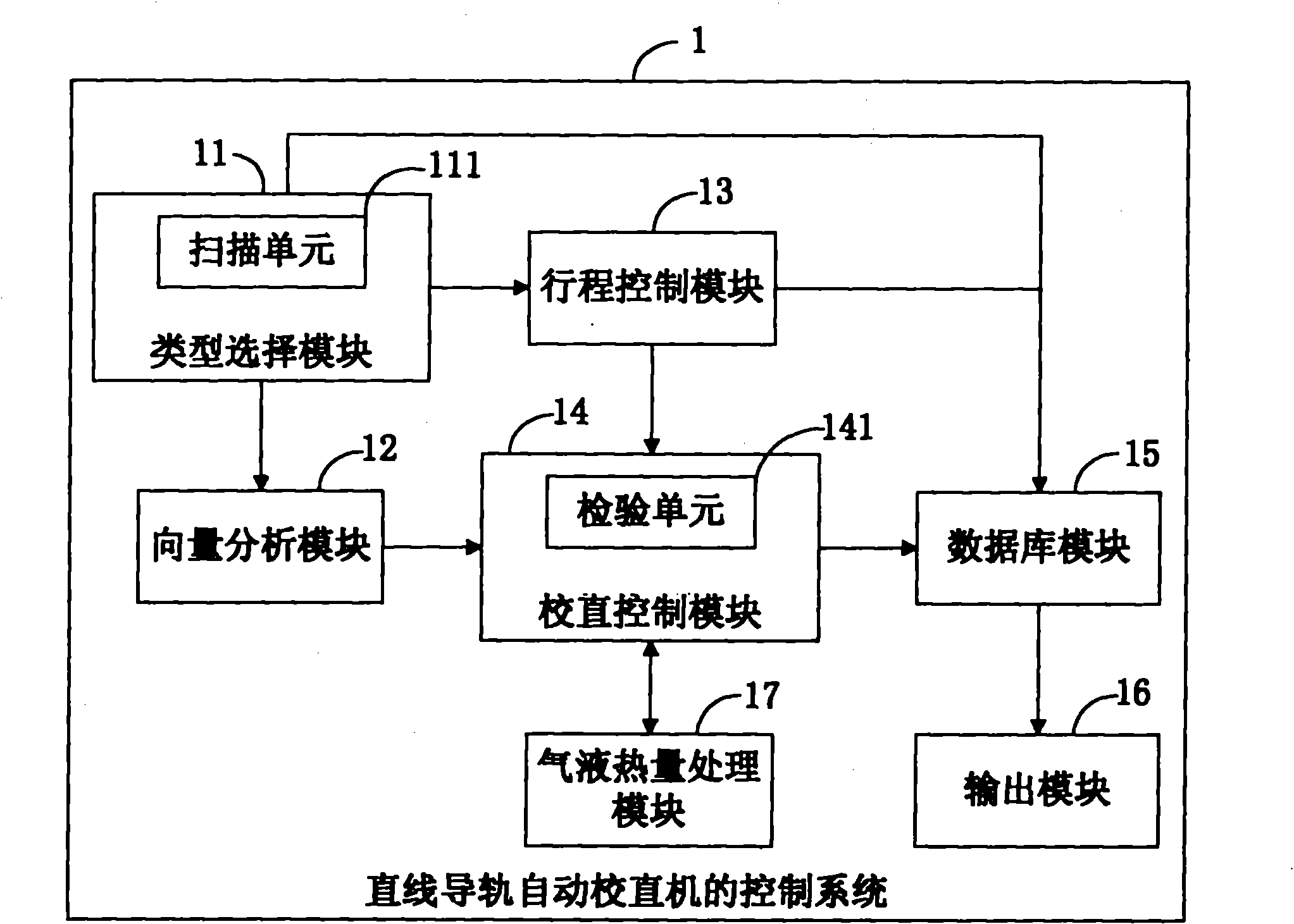
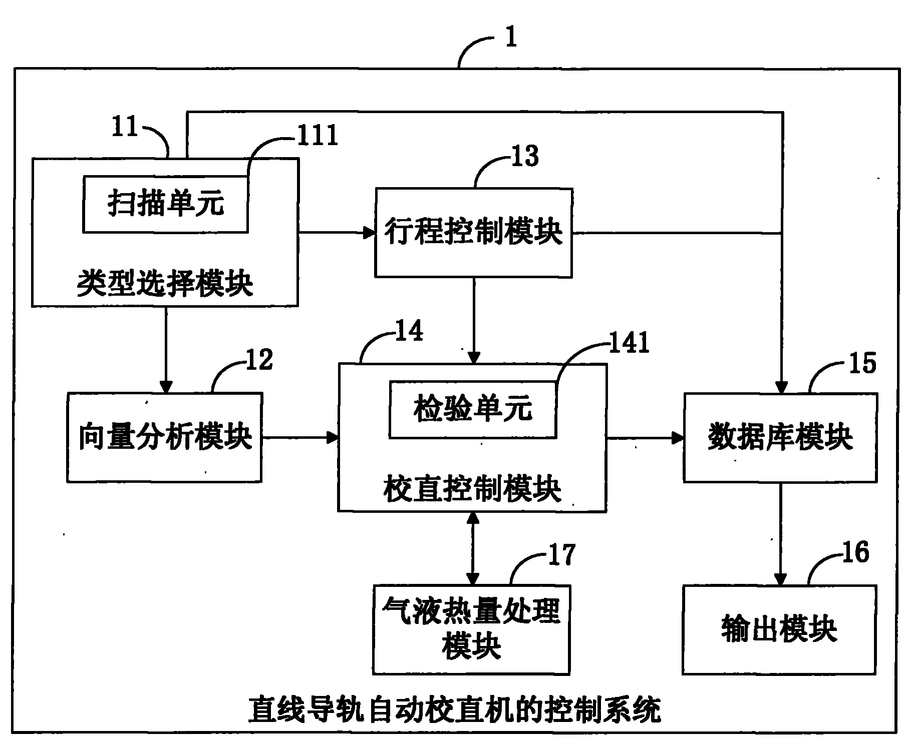
[0017] The present invention provides a control system for a linear guide rail automatic straightening machine. In this embodiment, the linear guide rail automatic straightening machine at least has a clamp for fixing the linear guide rail, and is used for pressing the positive curved surface of the linear guide rail into the Point correction pressure head, and two support members used to abut against the two supporting points of the n...


PUM


Abstract

The invention provides a control system of an automatic straightener for linear guide rails. The automatic straightener for the linear guide rails is at least provided with a straightening pressure head and two supporting parts. The control system firstly builds correction models of the linear guide rails in two vertical directions, connects measuring points positioned on a surface into a continuous curve, counts all curves on the linear guide rails, determines the position coordinates of pressure points of a positive curved surface and two supporting points of a negative curved surface and successive pressing sequences of curve segments according to the curvature of the curve segments, sets the maximal correction quantity of the straightening pressure head and the two supporting parts, then drives the two supporting parts to respectively support against the two supporting points of the negative curved surface of a selected curve segment so that the straightening pressure head presses the pressure points of the positive curved surface of the selected curve segment to carry out straightening operation and saves the correction models, the maximal correction quantities and straightening logs of the linear guide rails to carry out journey compensation variation and data correction when straightening the curve segment of a more secondary priority level so as to carry out high-accuracy and high-efficiency straightening on the linear guide rails.

Description

technical field [0001] The invention relates to the straightening technology of linear guide rails, in particular to a control system of a linear guide rail automatic straightening machine with high precision and high efficiency. Background technique [0002] In many fields of the machinery industry, linear guides are used in many production lines or machine tools to transfer tools or related products required for production. In the manufacture of linear guide rails, the guide rails undergo bending deformation after quenching and grinding to reduce the amount of deformation. Therefore, straightening has become an indispensable process in the processing of linear guide rails. Especially for high-precision guide rails, even a small amount of bending will affect the processing accuracy of the subsequent process, and even cause the finished assembly to fail to meet the accuracy requirements. [0003] In the existing technology, the domestic equipment in the same industry still ...

Claims


Application Information

Patent Timeline
IPC IPC(8): B21D3/10
Inventor 陆弘道钱敏
Owner 上海莱必泰数控机床股份有限公司
Learn More